background image

3

It is the installer's responsibility to carry out a full safety and function assessment of the appliance

To reduce the risk of fire, electric shock or injury, read all the safety instructions and warning texts before 

using the appliance.

•  This unit is only designed for ventilation air in buildings.

•  It must not be used to extract combustible or flammable gases.

•  Remove the power plug before commencing any service and maintenance work.

•  Before opening the door, current to the unit must be turned off and the fans must have had time to stop (min. 3 mins.).

•  The unit contains heating element which must not be touched when it is hot.

•  The unit must not be operated without the filters being in place.

•  Do not cook substances which could catch fire under the ventilator.

•  Do not leave a saucepan or frying pan containing oil or grease unsupervised. 

•  Follow the instructions in the user manual.

To maintain good indoor air quality, comply with regulations and to avoid condensation damage the unit must never be stopped 

apart from during service/maintenance or in connection with an accident.

 important Safety instructions:

!

According to IEC/EN 60335-1

Note that the product is not designed for operation by person with impaired  

physical, motor or mental abilities. The product must also not be used by 

persons who lack experience or knowledge, unless they have received guid-

ance or instructions in operating the product safely by a person responsible 

for safety.

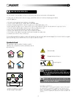
EXAMPLE OF NIPPLE LOCATION 

(shown as right-hand model)

HIGH VOLTAGE

DANGER! DO NOT TOUCH

Symbols Used

These products bear a number of symbols used for 

labelling the actual product and in installation and user 

documentation.

NB! 

When a text bears this symbol, damage to 

equipment or a poor utilisation ratio may result if 

instructions are not followed.

CAUtiON 

When a text bears this symbol, it 

means that personal injury or serious damage to 

the equipment may result if the instructions are 

not followed.

!

1

1

2

2

3

3

4

4

5

5

6

6

A

A

B

B

C

C

D

D

Date

Status

Description

Project

Stocknumber

Drawn

Approved

Projection

Scale

Replaces:

Replaced by:

24.03.2009

leif

Etikett sikkerhetsbryter

G2-1A

102732

2:1

102732

Type:

Material:

Colour:

Adhesiv:

Opaque

Glossy vinyl

White

Permanent

35,0

14

,0

SAFETY SWITCH

Summary of Contents for Spirit K2R

Page 1: ...102608E 01 2009 10 User manual and installation instructions Air handling unit with kitchen hood Flexit SPIRIT K2 R ...

Page 2: ... 2 Electrical work 13 7 3 Automatic Control 13 7 4 External components 13 8 Sizes Physical Dimensions 14 8 1 Dimensioned sketch 14 9 General Drawings and System Drawings 15 10 Capacity and sound data 16 10 1 Capacity diagram sound data specifications K2 R AC 16 10 2 Capacity diagram sound data specifications K2 R EC 17 11 Technical data 18 12 Adjusting the Kitchen Hood 19 12 1 Forced Ventilation 1...

Page 3: ...apart from during service maintenance or in connection with an accident Important Safety Instructions According to IEC EN 60335 1 Note that the product is not designed for operation by person with impaired physical motor or mental abilities The product must also not be used by persons who lack experience or knowledge unless they have received guid ance or instructions in operating the product safe...

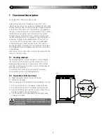
Page 4: ...g by the thermostat F20 which switches off at 60 C As an additional safety measure the thermostat F10 switches off at 85 C Thermostat F10 needs to be reset manually by pressing the reset button You will find the thermostat by opening the unit doors located directly over the heating element 1 2 Operation of kitchen hood A Knob for damper and for forced ventilation B Pushbutton for light When cookin...

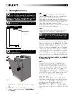
Page 5: ...ces When changing the filter check that the whole unit is working normally Rotor As the unit has filters with a high impermeability class installed it is not usually necessary to clean the rotor If for various reasons it should still be necessary dust can be removed with a soft brush Further cleaning is possible if you remove the rotor spray it with fat soluble detergent and then blow it clean fro...

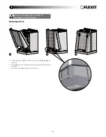
Page 6: ... Description Project Stocknumber Drawn Approved Projection Scale Replaces Re 12 02 2009 leif 351600_ C C 1 2 1 1 2 2 3 3 4 4 5 5 6 6 A B C D Date Status Description Project Stocknumber Drawn Approved Projection Scale Replaces Replaced by 12 02 2009 leif 351600_dør3 C 1 2 3 Mounting of door 1 Lower the front edge of the door into the leading edge of the unit 2 The guide pins on the door must pass t...

Page 7: ...er 1 2 3 4 B C D 2 3 Fig 5 1 1 2 2 A B C D e t s u t a n o i t p i r c s t c e j o r e b m u n k c o n w a r D d e v o r p p A n o i t c e j o r P e l a c S s e c a l p e R y b d e c a l p e R 9 0 0 2 2 0 8 f i e l 0 0 6 1 5 3 3 Fig 4 2 2 3 3 4 4 5 5 6 6 A B C D e t a D s u t a t S n o i t p i r c s e D t c e j o r P r e b m u n k c o t S n w a r D d e v o r p p A n o i t c e j o r P e l a c S 9 0...

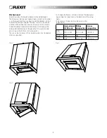
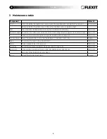
Page 8: ...ie in against the heat exchanger 12 months Make sure that rotor driving belt is in good condition and well adjusted 12 months Kitchen hood Wash the grease filter Check that the damper is clean and closes fully 2 weeks Seals Check that the seals in the unit are intact 12 months Valves To be cleaned at least once a year 12 months Air intake Check that no leaves and other items are caught in the gril...

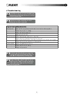
Page 9: ...pen door Type of fault Remedial action Cold draughts Check which supply temperature has been selected See operating panel Check that the rotor is rotating Check that heating comes on Needs new extract filter Fans not working Check that the power to the unit is connected Check that the overheating thermostat has not cut out Reset by pressing the button Also needs correcting on the automatic control...

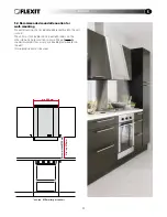
Page 10: ...s and only take service needs into account National statutory requirements for electrical safety may deviate from this Check which rules apply in your country 5 3 Location requirements The unit has been designed for location in the kitchen over the cooker as it contains an integrated kitchen hood The unit is available in left or right versions exhaust air nipple to the left or right depending on w...

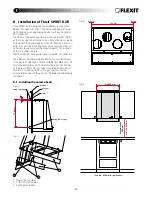
Page 11: ...ust not be placed on a wall with rooms on the other side which are sensitive to noise The wall must be sound insulated If necessary use double plasterboards on the wall Interrupted studs must be used For fitter 40 mm 720 mm min 600 mm spikerslag gips steinull min 500 650 mm Recommended 500mm min req 650mm for gas cookers Min req 450mm ...

Page 12: ...st have good sound insulation see Chap 6 4 The wall must be completely flat behind the ventilation unit If the kitchen hood area is tiled a suitable liner plate must be mounted behind the unit The distance between the bottom of the grease filter and the cooker should be at least 50 cm for electric cookers and 65 cm for gas cookers For the external dimensions of the unit see the dimensioned drawing...

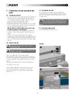
Page 13: ... cap so that any water that enters drains out again If there is a short distance between the unit and the exhaust point sound insulation must be installed to ensure that the requirements for the outdoor sound level are met Ducts must have good sound insulation particularly above the unit 7 2 Electrical work The unit is suppied with a 1 8 m cable with plug The cable leaves the top of the unit and i...

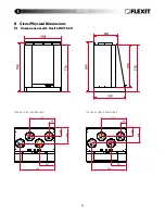
Page 14: ...14 8 Sizes Physical Dimensions 8 1 Dimensioned sketch Flexit SPIRIT K2 R For fitter Shown as right hand model Shown as left hand model 514 227 371 84 129 229 514 227 371 84 129 229 ...

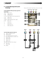
Page 15: ...ustment System drawing electric battery B1 Supply air temperature sensor EB1 Heating element F10 Overheating thermostat manual reset F20 Overheating thermostat automatic reset FI1 Supply air filter FI2 Extract air filter M1 Supply air fan M2 Extract air fan HR R Rotary wheel type heat exchanger M4 Rotor motor K Kitchen hood DA4 Damper DA4 K FI1 M1 M2 EB1 F10 F20 M4 FI2 B1 HR R Outdoor Supply Extra...

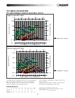
Page 16: ...er level LwA in the capacity diagrams and is corrected with the table below for the various octave bands Radiated noise produces Lw in the various octave bands and total LwA This is read directly from the supply air table Correction factor for Hz 63 125 250 500 1000 2000 4000 8000 LwA Supply air 3 2 2 5 5 6 13 29 Extract air 18 14 1 12 14 28 37 43 Radiated 46 39 29 36 40 44 54 58 33 5 Extract air ...

Page 17: ...wA in the capacity diagrams and is corrected with the table below for the various octave bands Radiated noise produces Lw in the various octave bands and total LwA This is read directly from the supply air table Correction factor for Lw Hz 63 125 250 500 1000 2000 4000 8000 LwA Supply air 3 2 2 5 5 6 13 29 Extract air 18 14 1 12 14 28 37 43 Radiated 41 35 33 39 40 49 50 60 33 5 Extract air side wi...

Page 18: ...an motor control Transformer 0 10 V Max fan speed 2 500 RPM 1 970 RPM Automatic control standard CS 50 CS 50 Filter type SUP EXTR F7 F7 F7 F7 SUP filter dimensions WxHxD 130x335x50 mm 130x335x50 mm EXTR filter dimensions WxHxD 130x335x50 mm 130x335x50 mm Weight 56 kg 56 kg Duct connection Dia 125 mm sleeve Dia 125 mm sleeve Duct connection kitchen fan Height 700 mm 700 mm Width 598 mm 598 mm Depth...

Page 19: ...even more air through the kitchen hood 3 Turn the knob to position 3 This will give a fully open damper which will allow even more air through the kitchen hood in that the fans go to speed 3 4 The air volume through the unit can also be increased by setting the fans to speed 3 via the control panel external panel See separate instructions The damper needs closing again manually There is no timer i...

Page 20: ...ntilation Flexit SPIRIT K2 R Max air volume through kitchen hood in case of forced air volume For fitter Measurements have been taken at 2 3 pressure in the extract air duct and 1 3 pressure in the exhaust air duct before opening the damper ...

Page 21: ...t operates normally at all stages Heating switches in The unit has filters for both outdoor air and extract air Tumble dryers must not be connected to the unit The installer may be held liable for any incorrect or defective installation Flexit SPIRIT K2 R Right hand model For fitter Flexit SPIRIT K2 R Left hand model 14 1 First use Check that the control panel has been connected Plug the unit into...

Page 22: ...th the existing terms of sale provided that the product is used and maintained correctly Filters are consumables The symbol on the product shows that this product must not be treated as household waste It must be taken to a reception station for recycling of electric and electronic equipment By ensuring the correct disposal of the equipment you will contribute to preventing the negative consequenc...

Page 23: ...23 ...

Page 24: ...Flexit AS Televeien 15 1870 Ørje Norway www flexit com ...

Reviews: