9
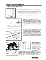
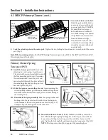
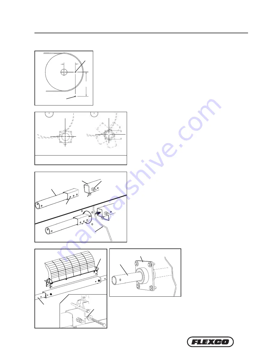
5. Install the mounting bases.
Bolt the mounting bases to the
chute with the bolts provided
(Fig. 5).
6. Install the blade cartridge.
Place the blade cartridge onto
the centre pole. Adjust the
extender poles until the holes
align with the holes in
the centre pole and lock the cartridge into place with the two bolts,
washers and nuts (Fig. 6). NOTE: Be sure at least 150mm of the extender
pole extends out of the mounting base on each side for tensioner
installation. Adjust the extender poles in the centre pole if more or less
length is needed.
Section 4 – Installation Instructions
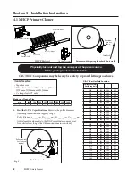
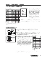
2. Lay out the dimensions on the chute wall. Measure out the X dimension
horizontally from the centre of the pulley shaft and mark. (NOTE: It may be
easier to put a level on top of the pulley shaft, draw a horizontal line and then
measure down half the diameter of the shaft and make a line from the front of
the shaft. Now subtract half the pulley shaft diameter from the X coordinate
and measure on the line and make a mark.) Then measure down vertically the
Y dimension and mark. This is the correct position for the centre of the cleaner
pole (Fig. 2). Lay out and mark the same dimensions on the other side.
3. Mark and cut the mounting base holes. Using the
mounting base template provided in the instruction packet,
position the large pole hole of the template on the chute with
the hole notches aligned with the layout lines. Trace the pole
hole and mounting holes (Fig. 3). Each base can be mounted
in any position 360° around the pole as long as the pole’s
centre point does not change. Cut the holes on both sides of
the chute.
4. Assemble the extender poles to the centre pole. Insert the
extender poles through the chute holes and into the centre
pole and make sure the locating bolt holes align with the
centre pole holes (holes are offset to the lower half). Position
the centre pole with the welded nuts and locking bolts on
one side facing down and on the adjoining side facing away
from the head pulley (Fig. 4). Leave the locking bolts loose.
4. 1 MHCP Primary Cleaner (cont.)
mark
Y
X
mark
Center large template hole notches on pole center mark,
rotate to desired angle and trace holes
Template for
PST mounting base
Template for
AWT/NT mounting base
Blade
Cartridge
6" of pole end
must extend
outside the
mounting base
on each side
Align holes
and install
bolts, washers
and nuts
Extender
Pole
Mounting Plate
(Pst Shown)
Chute wall
(cut away)
Chute wall
(cut away)
Center Pole
Extender Pole
Must be facing
away from
head pulley
Locating bolt
holes
Locking
Bolts
Must align with
extender pole
holes
Must be
facing down
Fig. 2
mark
Y
X
mark
Center large template hole notches on pole center mark,
rotate to desired angle and trace holes
Template for
PST mounting base
Template for
AWT/NT mounting base
Blade
Cartridge
6" of pole end
must extend
outside the
mounting base
on each side
Align holes
and install
bolts, washers
and nuts
Extender
Pole
Mounting Plate
(Pst Shown)
Chute wall
(cut away)
Chute wall
(cut away)
Center Pole
Extender Pole
Must be facing
away from
head pulley
Locating bolt
holes
Locking
Bolts
Must align with
extender pole
holes
Must be
facing down
Fig. 3
mark
Y
X
mark
Center large template hole notches on pole center mark,
rotate to desired angle and trace holes
Template for
PST mounting base
Template for
AWT/NT mounting base
Blade
Cartridge
6" of pole end
must extend
outside the
mounting base
on each side
Align holes
and install
bolts, washers
and nuts
Extender
Pole
Mounting Plate
(Pst Shown)
Chute wall
(cut away)
Chute wall
(cut away)
Center Pole
Extender Pole
Must be facing
away from
head pulley
Locating bolt
holes
Locking
Bolts
Must align with
extender pole
holes
Must be
facing down
Fig. 4
mark
Y
X
mark
Center large template hole notches on pole center mark,
rotate to desired angle and trace holes
Template for
PST mounting base
Template for
AWT/NT mounting base
Blade
Cartridge
6" of pole end
must extend
outside the
mounting base
on each side
Align holes
and install
bolts, washers
and nuts
Extender
Pole
Mounting Plate
(Pst Shown)
Chute wall
(cut away)
Chute wall
(cut away)
Center Pole
Extender Pole
Must be facing
away from
head pulley
Locating bolt
holes
Locking
Bolts
Must align with
extender pole
holes
Must be
facing down
Fig. 5
Fig. 6
Blade
Cartridge
150 mm of pole
end must extend
outside the
mounting base
on each side
Align holes
and install
bolts, washers
and nuts


