19
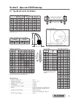
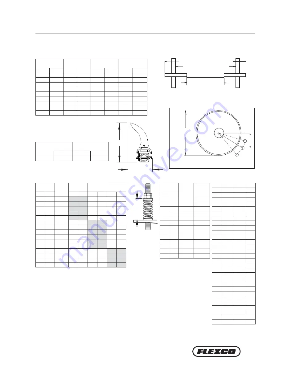
8.1 Specifications & Guidelines
Clearance Guidelines for Installation
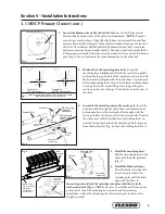
Horizontal
Clearance Required
Vertical
Clearance Required
mm
in.
mm
in.
175
7
475
19
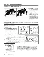
Telescoping Pole Length Specifications
Cleaner Size
Max Overall
Pole Length
Centre Pole
Length
Maximum
Conveyor Span
mm
in.
mm
in.
mm
in.
mm
in.
600
24
2050
82
700
28
1650
66
750
30
2200
88
850
34
1800
72
900
36
2350
94
1000
40
1950
78
1050
42
2500
100
1150
46
2100
84
1200
48
2650
106
1300
52
2250
90
1350
54
2800
112
1450
58
2400
96
1500
60
2950
118
1600
64
2550
102
1800
72
3250
130
1900
76
2850
114
2100
84
3550
142
2200
88
3150
126
Pole Diameter - 73mm
Pole Location Chart
A
X
Y
C
500
254
365
445
525
267
365
451
550
279
365
460
575
292
365
467
600
305
365
476
625
318
365
483
650
330
365
492
675
343
365
502
700
356
365
511
725
368
365
518
750
381
365
527
775
394
365
537
800
406
365
546
825
419
365
556
850
432
365
565
875
445
365
575
900
457
365
584
925
470
365
594
950
483
365
606
975
495
365
616
1000
508
365
625
1025
521
365
635
1050
533
365
648
1075
546
365
657
1100
565
365
673
1125
581
365
686
1150
597
365
699
1175
610
365
711
1200
625
365
724
Specifications:
• Maximum Belt Speed ..........................................6 m/s
• Temperature Rating .............................................-35°C to 82°C
• Minimum Pulley Diameter ................................500 mm
• Blade Height .........................................................350 mm
• Useable Blade Wear Length ................................200 mm
• Blades .................................................................... Polyurethane (proprietary blend for
abrasion resistance and long wear).
• Available for Belt Widths .................................... 600 to 2100 mm
Other sizes available upon request.
• CEMA Cleaner Rating ........................................Class 5
Maximum Overall Pole Length
Maximum Conveyor Span
Centre Pole Length
Top of
washer to
top of
torque
arm
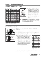
Pole Location Specs
A = Pulley Di Lagging and Belt
C = Critical Spec to move location if necessary
A
X
C
Y
Move Dim. C
on arc
Section 8 – Specs and CAD Drawings
Vertical
Horizontal
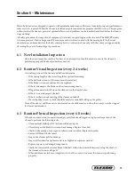
Spring Length Chart
Blade
Width
No. Of
Blades
White
Springs
Silver
Springs
Red
Springs
mm
in.
mm
in.
mm
in.
mm
in.
450
18"
3
146
5 3/4"
162
6 3/8"
165
6 1/2"
600
24"
4
137
5 3/8"
159
6 1/4"
162
6 3/8"
750
30"
5
130
5 1/8"
156
6 1/8"
162
6 3/8"
900
36"
6
121
4 3/4"
156
6 1/8"
159
6 1/4"
1050
42"
7
114
4 1/2"
152
6"
159
6 1/4"
1200
48"
8
N/A
N/A
149
5 7/8"
156
6 1/8"
1350
54"
9
N/A
N/A
146
5 3/4"
156
6 1/8"
1500
60"
10
N/A
N/A
146
5 3/4"
152
6"
1650
66"
11
N/A
N/A
144
5 5/8"
152
6"
1800
72"
12
N/A
N/A
140
5 1/2"
149
5 7/8"
1950
78"
13
N/A
N/A
130
5 1/8"
146
5 3/4"
2100
84"
14
N/A
N/A
N/A
N/A
146
5 3/4"
2250
90"
15
N/A
N/A
N/A
N/A
144
5 5/8"
2400
96"
16
N/A
N/A
N/A
N/A
140
5 1/2"
2550
102"
17
N/A
N/A
N/A
N/A
140
5 1/2"
Spring tension is based on the number of blades on the cleaner, not the
belt width. Shading indicates preferred spring option.
Pressure Chart
Blade
Width
No. of
Blades
kPa
mm
in.
450
18"
3
55.2
600
24"
4
69.0
750
30"
5
89.6
900
36"
6
103.4
1050
42"
7
124.1
1200
48"
8
137.9
1350
54"
9
158.6
1500
60"
10
172.4
1650
66"
11
193.1
1800
72"
12
213.7
1950
78"
12
227.5
2100
84"
14
248.2
2250
90"
15
262.0
kPa setting is based on the number
of blades on the cleaner, not the
belt width.

