


Installation, Operation, & Maintenance Guide
Vantage Series
SHEET 1 OF 1
DWG NO:
FS27151-CST-028
SIZE
DRAWN BY:
291 Hurricane Lane
Williston, VT 05495
(802) 878-8307
TITLE:
SURFACE MUST BE CONCENTRIC
PARALLEL, FLAT, SQUARE AND
TRUE AS APPLICABLE TO EACH
OTHER WITHIN .002" TOTAL
INDICATOR READING UNLESS
OTHERWISE SPECIFIED.
DATE:5/15/2020
REV:
1 3/4
A
UNLESS OTHERWISE SPECIFIED
DECIMALS: .005
FRACTIONS: .015
ANGLES: 1/2"
REMOVE ALL BURRS
CHAMFER ALL CORNERS
.010/.020 X 45
A
GLAND
MATERIAL:316 SS / CF8M
DESIGNED BY:
CHECKED BY:
JOB NO.:GEN V
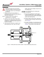
Port 2:
Buffer/Barrier Fluid In
Clockwise Rotation
Port 1:
Preferred Buffer/Barrier Fluid Out
Bidirectional
Port 3:
Preferred Buffer/Barrier Fluid In
Bidirectional
Port 4:
Buffer/Barrier Fluid Out
Clockwise Rotation
Figure 11: Vantage Series Double Cartridge Seal Port Locations
•
All ports not used for buffer/barrier fluid system must be plugged.
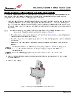
Figure 12: Typical Installation of a Buffer/Barrier Fluid Reservoir
Page 7 of 10


