background image

Installation, Operation, & Maintenance Guide

Vantage Series

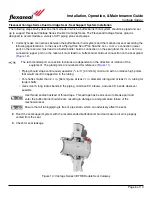
Flexaseal Vantage Series Dual Cartridge Seal - Seal Support System Installation

The following steps briefly describe the methods in which a buffer/barrier fluid system should be piped and set
up to support Flexaseal Vantage Series Double Cartridge Seals. The Flexaseal Vantage Series gland is
designed to accommodate a variety of API piping plans and pumps.

1

. Correctly make connections between the buffer/barrier fluid system and the mechanical seal according the

following specifications. In the case of a Piping Plan 52 or Plan 53A the

SEAL SUPPLY

connection (lower

port) on the reservoir must lead to a buffer/barrier fluid in connection on the seal gland; the

SEAL RETURN

connection (upper port) on the reservoir must lead to a buffer/barrier fluid out connection on the seal gland.
(

Figure 12

).

The recomended port connection locations are dependent on the direction of rotation of the

equipment. The gland ports are numbered for reference (

Figure 11

).

• Piping should slope continuously upwards (

1

2

in./ft. [40 mm/m] minimum) with no relative high points

that would result in trapped air in the tubing.

• For shafts smaller than 2

1

2

in. [64 mm] use at least

1

2

in. diameter tubing and at least

3

4

in. tubing for

larger shafts.

• Use smooth, long radius bends in the piping, minimize 90

elbows, and use 45

bends wherever

possible.

Use thread sealant instead of thread tape. Thread tape has been known to break apart and
enter the buffer/barrier fluid stream, resulting in damage to and premature failure of the
mechanical seal.

Ensure that all tubing/piping is free of pipe strain, which can adversely affect the seal.

2

. Flood the seal support system with the recommended buffer/barrier fluid and ensure all air is properly

vented from the seal.

3

. Check for seal leakage.

Figure 10: Vantage Series VBTRB Double Seal Cutaway

Page 6 of 10

Summary of Contents for VANTAGE Series

Page 1: ...Avenue Houston Williston VT 05495 Bom Retiro Sao Paulo Gonzales LA 70737 7545 E Orem Drive Brazil CEP 01130 010 Houston TX 77075 TEL 832 804 7424 TEL 802 878 8307 TEL 55 11 3736 7373 TEL 225 484 0007...

Page 2: ...al installation operation and maintenance must only be carried out by qualified personnel who have thoroughly read all instructions 3 The seal must only be used for its intended application Flexaseal...

Page 3: ...e shaft shaft sleeve if present and seal chamber face of rust burrs grit sharp edges and set screw damage using fine emery cloth Wipe clean Avoid making flat spots or reducing the shaft diameter 4 If...

Page 4: ...nout 0 0015 0 003 in Fig 3 Radial bearing fit 0 002 0 003 in Fig 4 Bearing frame perpendicularity 0 0005 in in Fig 5 Axial shaft movement end play 0 003 in Fig 6 Seal chamber bore concentricity 0 005...

Page 5: ...ket facing but clear of the seal chamber 6 Reassemble the pump as described by the pump OEM 7 If the gland is equipped with a gland gasket lubricate gland bolts and bolt the gland to the seal chamber...

Page 6: ...RUE AS APPLICABLE TO EACH OTHER WITHIN 002 TOTAL INDICATOR READING UNLESS OTHERWISE SPECIFIED DATE 5 15 2020 A UNLESS OTHERWISE SPECIFIED DECIMALS 005 FRACTIONS 015 ANGLES 1 2 REMOVE ALL BURRS CHAMFER...

Page 7: ...gland Figure 12 The recomended port connection locations are dependent on the direction of rotation of the equipment The gland ports are numbered for reference Figure 11 Piping should slope continuous...

Page 8: ...5 FRACTIONS 015 ANGLES 1 2 REMOVE ALL BURRS CHAMFER ALL CORNERS 010 020 X 45 A GLAND MATERIAL 316 SS CF8M DESIGNED BY CHECKED BY JOB NO GEN V Port 2 Buffer Barrier Fluid In Clockwise Rotation Port 1 P...

Page 9: ...NCE If leakage is detected it should be addressed as soon as possible to protect personnel and prevent hazards Leakage could come from a number of leak paths in the seal or be caused by changes in the...

Page 10: ...ins and hazardous products must be reiterated Make note of all fluids contained in the pump drain and decontaminate before opening the housing for seal service 1 Ensure all fluid has been drained and...

Page 11: ...ject to misuse misapplication neglect alteration accident or physical damage c have been used in a manner contrary to FAS s instructions for installation operation and maintenance d have been damaged...

Reviews: