Flash Technology
Revision A - 2/13/2020
18
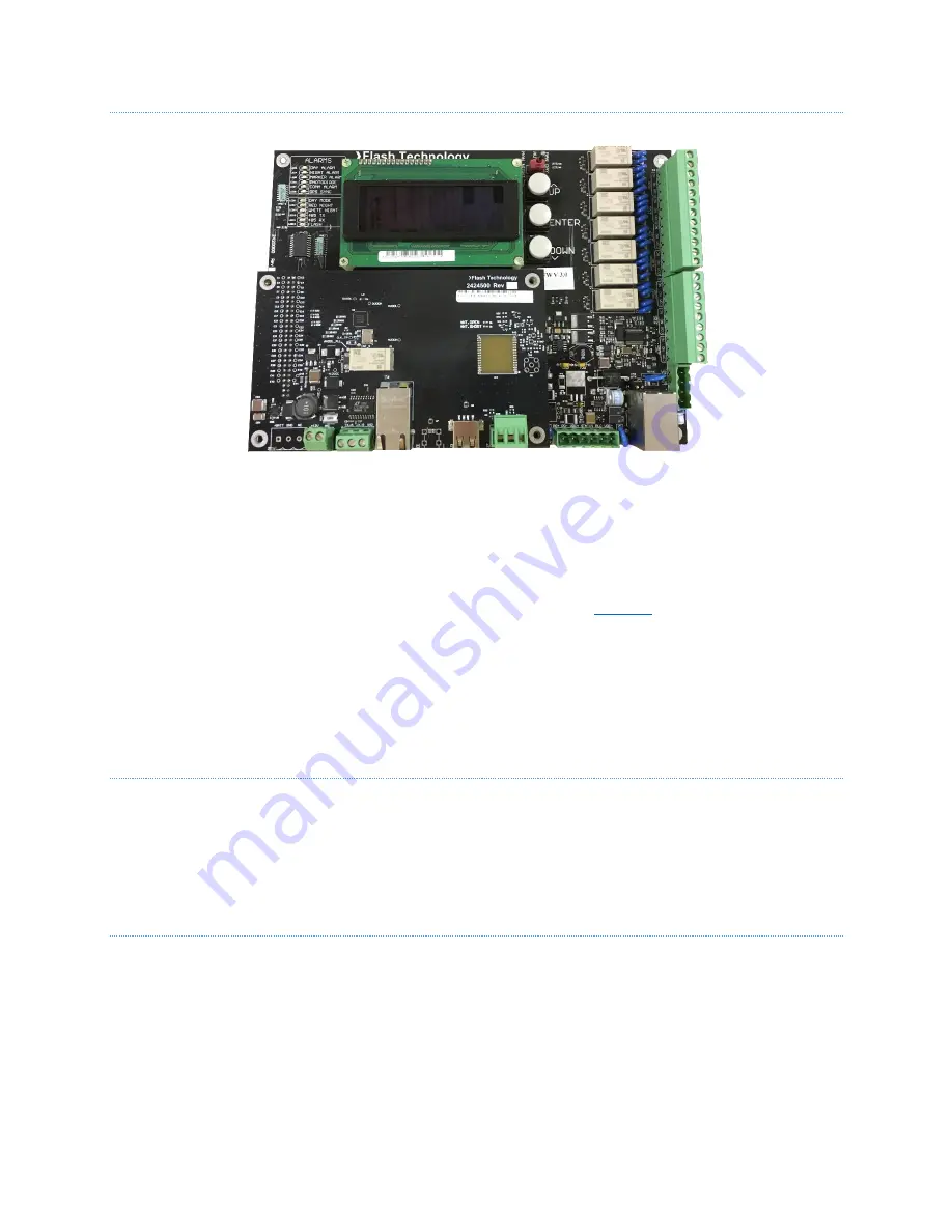
PCB1 DISPLAY BOARD
The display board (PCB1) provides a direct user interface to the system’s status, configurations and diagnostic
features. A User Interface with alphanumeric display and push-buttons provides system configuration and alarm
notification. The PCB1 also comes equipped with six standard dry contacts for remote alarm monitoring. A mode
override switch also enables a 30-minute tower operating mode override.
The PCB1 provides system status, alarm and programming information. The information display defaults to show
the current system status as well as the basic configuration for the unit. See
for a detailed description for
all menu functions of the information display.
The FTC 270 has additional add-on options, which include:
Cellular Modem
Local Wi-Fi Antenna
PCB6 Alarm Relay Expansion Board
PCB2 TOWER CONTROLLER BOARD
The tower controller board (PCB 2) controls the operating mode and flash synchronization of all lights in the tower
system. It does so by communicating with the controller boards in the various light units over an isolated RS-485
bus. A GPS antenna connected to PCB2 provides time and location information to the controller. This information
is used as a mode change backup using sunrise/sunset data to change the operating mode in case of a photodiode
failure.
PCB3 SMART BOARD
The smart board (PCB3) comes standard with the FTC 270. This allows the user to monitor and control the system
remotely, and receive full diagnostic information through an LTE modem or Ethernet-based connectivity; SNMP,
Modbus or Eagle protocols may be used. The PCB3 also provides the ability to read a USB drive for the purposes of
updating firmware versions. The PCB3 also allows an optional Wi-Fi interface to the lighting system, using a long-
range external antenna, or a short-range internal USB Wi-Fi dongle.


