5
4
SPECIALIZED
HEALTHY
AIR SOLUTIONS
SPECIALIZED
HEALTHY
AIR SOLUTIONS
OWNER’S MANUAL
OWNER’S MANUAL
ASCENDANT
™
ASCENDANT
™
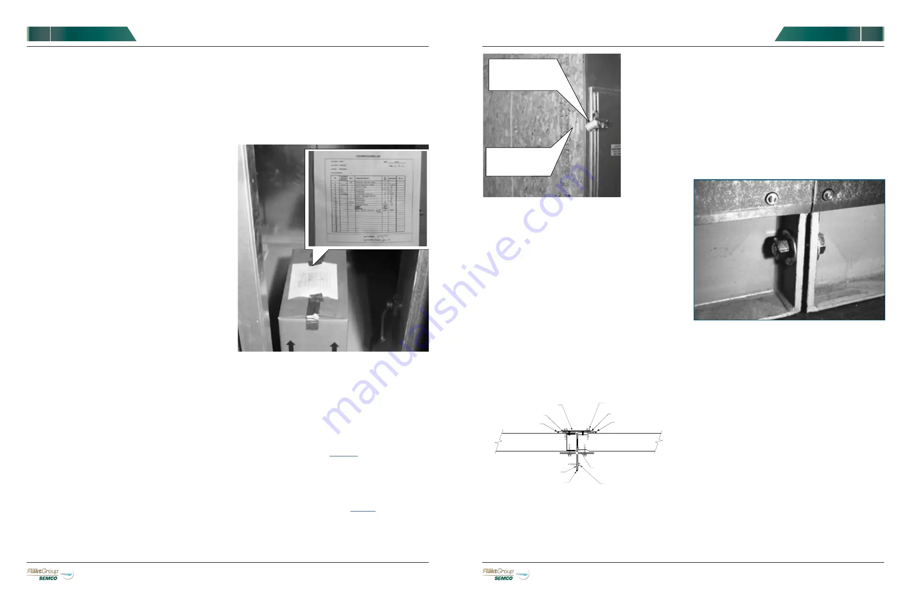
FIGURE 4.
All gaskets, bolts, and other items required for
installation are shipped in a box located in the supply air
compartment. On top of the box you will find a packing list.
STORAGE
INSPECTION
In addition to inspecting modules and equipment
visually for possible shipping damage, be sure to
consult “Inspection” instructions described later in this
manual for each optional component.
exposed to still more grime on the construction
site. Therefore, it is imperative that the exterior
of each module be washed down with soap and
water soon after it arrives. Abrasives and solvents
should not be used without first consulting
FläktGroup SEMCO.
4)
The interior of each module should also be
cleaned throughly and all equipment should be
lubricated before storing or beginning operation.
5)
See other sections for specific lubrication
instructions.
If the system, or parts thereof, must be stored before
installation, indoor storage is preferred. If not possible,
modules should be located on a hard surface with
adequate drainage so that water cannot accumulate
under the modules. A solid paved surface would be
appropriate. Modules must be stored on blocks or
timbers that raise modules at least four inches above
the ground.
If stored indoors, modules should be protected from
damage. If stored outdoors, modules must be covered
with well-anchored canvas tarps. Heavy-mil plastic
tarps should be used with caution as they can trap
moisture against the unit.
MOISTURE MUST NOT BE ALLOWED TO ENTER THE
MODULES.
Whether stored indoors or outdoors,
all openings must be closed tightly and piping
penetrations must be capped. However, drain
connections should be left open.
As noted previously, modules must be washed to
remove corrosive materials and dirt before storage.
During the storage period, modules should be opened
and inspected every 30 days. Fans must be inspected
and rotated a few times by hand and stopped in a
position other than the original position. Fans should
also be lubricated as prescribed on the fan label.
INSTALLATION
1)
Prepare the installation site by cleaning it of all
debris. Supports, which the modules will be
installed on, should be level. The unit base is
designed either for mounting on a concrete pad or
onto a roof curb (See
).
2)
Consult drawings and submittal provided to
determine the location of each module. Plan to
lift modules in the order required for your
Installation and within the limitations of your lifting
equipment (see
LIFTING
3) Adjoining ends of modules are covered with
plywood and/or plastic sheets during transport.
This must be removed prior to hoisting the
modules in place. (See
FIGURE 6
).If installation
FIGURE 5.
Module sides which are to be joined at time of installation are
covered with plywood and/or plastic sheets for protection
during transport.
Throughout the unit you will find instruction labels indicating
which steps MUST be performed for proper installation.
4)
Remove shipping restraints at roof joint (not
shown).
5)
Hoist the first module in place. Spreader bars and
hoisting lugs must be used on each module for
hoisting. Do not use forklifts. (See
FIGURES 1
and
2
on
PAGE 3
).
6)
After positioning the module correctly, install
continuous gasket material on field joint flange as
indicated in
FIGURE 6.
INSTRUCTION
LABEL
REMOVE
BEFORE
INSTALLATION
BUTT STRAP
TEK SCREW 12" O.C.
POLYURETHANE CAULK
POLYURETHANE CAULK
PANEL
GASKET BETWEEN JOINT
TEK SCREW 12" O.C.
POLYURETHANE CAULK
POLYURETHANE CAULK
POLYURETHANE CAULK
PANEL
GASKET
FIGURE 6.
Detail of field joint located on side.
FIGURE 7.
Field joint located on base. Use only these bolts to
pull the modules together!
7)
Hoist the second module by its lifting lugs
(continue to use spreader bars), and position it
close to the first module. After aligning with the
first module, move the second module against the
first module.
8)
Insert bolts that join the first two modules in the
unit base and tighten. The large bolts in the unit
base may be used to help pull the two modules
against each other. Do not use any of the internal
field joints to pull the units together.
(See
FIGURE 7
).
9)
Verify that the two modules are straight, square
and level. Use metal shims if necessary to level.
10)
Hoist and set succeeding modules as described
in
STEPS 5-7
.
If moisture is found in any module, it must be removed
immediately. The source of the moisture must be
determined and corrected immediately.
During storage, modules should not be stacked on top
of each other.
Boxes containing bolts, gaskets and other items
should be stored inside the modules (See
FIGURE 4
).
11)
If installation requires that some modules be
placed on top of base or bottom modules, be sure
to install continuous gaskets between upper
and lower modules as indicated in drawings and
submittals.
12)
Do not torque connecting bolts until all upper
modules are installed. Experience suggests
installing bolts in the following manner. First,
attach bolts that join the centers of connecting
modules. Then work outward from the center
and attach remaining bolts, which will assure
proper alignment. Bolts should only be tightened
by hand until all upper modules are in place.
Then they should be torqued to 25 ft-lbs.


