background image

FL

AIR

MO ApS 

 Lundeborgvej 3 

 DK-9220 Aalborg 

 Denmark 

Phone: +45 53717220 Web: www.flairmo.dk - E-mail: [email protected] 


9. Vacuum pump starts and stops more frequently than 
usual: 

a) Leaks. See point 4f. 
 

10. Vacuum pump does not start at minimum vacuum or 
does not stop at stop vacuum: 
The following points only apply to units with vacuum gauge: 

a) Vacuum switch defective. Replace. 
b) Vacuum switch is not adjusted correctly. Adjust correctly. 
 

11. Compressor does not switch on against pressure or 
does not switch off at max. pressure: 

a) Defective pressure switch. Replace. 
 

Test the non-return valve 
· 

Once a year. 

· 

Switch off compressor on the main switch and pull out the plug. 

· 

Pull the ring at the end of the safety valve (fig. 3). 


Warning: 
Loud noise! 
· 

Let pressure fall to 0 bar. The pressure is to be read on the 

pressure gauge for receiver pressure. 

· 

If the compressor is mounted with a TÜV-approved safety 

valve, the receiver is emptied by loosening the screw at the 
end of the safety valve. 

· 

Dismount non-return valve from receiver (fig. 4). 

· 

Disassemble non-return valve and clean it (fig. 5) 

· 

R

e-assemble and mount the non-return valve again


(fig. 4).


Preventive maintenance (all) 


Weekly 

Monthly 

Annually 

Drain condensate from air receiver. 
If equipped with autodrain, this will 
take place automatically, however, 
drain bottle has to be emptied.


If compressor is fitted with outlet 
filter, check and empty for water 
by pressing the black button at the 
bottom. If fitted with autodrain, this 
will take place automatically.


Check motor, air tubes, hoses and 
equipment for leaks, and check the 
pumping time.


Clean unit or wipe with a soft, damp 
cloth. If necessary, use paraffin on 
rag to remove sticky adhesions. 
Dust and dirt prevent cooling.


Check intake filter. Clean or replace 
if necessary. Min. annually or every 
2000 hours whichever comes first.


Check the O-ring in the non-return 
valve and replace, if necessary. 

Note! Empty receiver of air before 
dismounting.


Check filter and filter elements for 
optimum efficiency.


Test the safety valve by gently 
pulling the ring with pressure in the 
receiver.


Check the pumping time (Comp.) 

The pumping time indicates the condition of the compressor 
provided that there are no leaks in the system where the 
compressed air may leak. Test the compressor as follows: 
1. Empty the air receiver of compressed air (the pressure 
gauge shows 0 bar). 
2. Close the outlet on the air receiver and check that the drain 
cock is closed. 
3. Start the compressor and note how long it takes until it 
switches off. 
Ensure that the pressure in the air receiver is 8 bar/120 psi 
as deviations may indicate the wrong results. 

Pump up time for this compressor is approx. 60sek. 

 
Important! 
Always test the compressor when cold as the time 
indicated refers to the pumping time of a cold 

compressor. The pumping time of a warm compressor 
is much longer and consequently, the result would be 
misleading. 

 
Pressure vessel 

Directions for use 

Application: Receiver for compressed air. 
Receiver specifications: See name plate. 
Installation: Tubes, etc. must be made of suitable materials. 
Placement: Observe the working temperature of the receiver. 
Ensure that sufficient room for inspection/maintenance is 
available in a horizontal position. 
The receiver must be kept in a horizontal position.. 
Corrosion protection The surface treatment must be maintained  
as required. 
Internal inspection at least every 5 years. 
Drain moisture at least once a week. 
Alternation/repair No welding must be made on pressurized parts.. 
Safety valve Ensures that PS will not be exceeded. 
Never adjust to a higher pressure than PS. 
The capacity of the valve must be calculated in accordance 
with the volume of air supplied by the compressor. 
(PS = Maximum working pressure of the receiver) 
 

Declaration of Conformity 

NOTE: The declaration of conformity is only valid for units 
operating at 230 V/50 Hz, 3x400 V/50 Hz, 12 V DC or 24 V DC.  
 
The manufacturer, FLAIRMO ApS, declares that the products 
mentioned in this manual are in conformity with: 
• 87/404/EEC - 90/488/EEC - 93/68/EEC Council Directive 
relating to Simple Pressure Vessels 
• 98/37/EC Machinery Directive 
• 89/336/EEC EMC Directive 
• 73/23/EEC Low Voltage Directive 


Flemming Steen Petersen 
Teknisk Direktør 


Summary of Contents for OFCS-A100.25

Page 1: ...O ApS Lundeborgvej 3 DK 9220 Aalborg Denmark Phone 45 53717220 Web www flairmo dk E mail info flairmo dk Operator and service manual Compressor models FLAIRMO A38 4 A38 4W A38 24 A62 4 A62 24 A100 25 A200 25 ...

Page 2: ...chnical information ______________________________________________________ Reservedele Reservdelslista Spare Parts ______________________________________________________ Tegninger Billeder Bilder illustrationer Drawings Pictures ______________________________________________________ Notater Noter Notes ______________________________________________________ ...

Page 3: ...tien omfatter ikke skader som skyldes vold misbrug fejlagtige reparationer eller uoriginale reservedele Transportomkostninger er ikke omfattet af garantien For Skandinavien gælder iøvrigt NL 92 Salgs og Leveringsbetingelser FLAIRMO ApS forbeholder sig retten til ændringer i tekniske specifikationer konstruktion Kassens indhold kun motordelen Deres nye kompressor vakuumpumpe er leveret i en ren og ...

Page 4: ...p vakuumpumpen ved at dreje venstre skrue start stop vakuum mod uret 3 Åbn for indsugningen på beholderen for at igangsætte den automatiske start på vakuumpumpen 4 Luk for indsugningen på beholderen for at igangsætte det automatiske stop ved det ønskede vakuum 5 Fortsæt ovenstående procedure 1 4 indtil vakuumpumpen stopper ved det ønskede vakuum Eksempel Hvis det ønskede stopvakuum f eks er 450 mb...

Page 5: ...r beholderen er under tryk x Check oppumpningstider kompressor Oppumpningstiden kan give en indikation af kompressorens tilstand under forudsætning af at der ikke er lækager i anlægget hvor trykluften kan sive ud Testen udføres på følgende måde 1 Tøm beholderen for komprimeret luft manometeret viser 0 bar 2 Luk for afgangen på beholderen og check at drænhanen er lukket 3 Start kompressoren og kont...

Page 6: ... rätten till ändringar i tekniska specifikationer konstruktioner Innehåll i emballagelåda endast motor Din nya kompressor vakuumpump ska levereras i en ren och oskadad emballagelåda Om ej kontakta din leverantör omedelbart Emballagelådan ska innehålla följande Installation endast motor Er FLAIRMO kompressor är mycket lätt att använda Följer Ni våra instruktioner kommer Ni att ha många års glädje a...

Page 7: ...lls vakuumpumpen stannar vid önskat vakuum Exempel Om det önskade vakuumstoppet är t ex 300 mbar startar vakuumpumpen ej före ett vakuum på ca 450 mbar Differensen på 150 mbar motsvarar inställningen på differensskalan 450 mbar motsvarar 0 45 på vakuum mätaren Felsökning och reparation alla Viktigt Bryt strömmen före varje ingrepp i kompressorn Töm behållaren på luft före varje ingrepp i kompresso...

Page 8: ...örutsättning att det ej är läckage i anläggningen där tryckluften kan läcka ut Testet utförs enligt följande beskrivning 1 Töm behållaren på komprimerad luft manometern visar 0 bar 2 Stäng avtappningskranen och kontrollera att dräneringskranen är stängd 3 Starta kompressorn och kontrollera tiden tills den stannar igen via pressostaten Observera att tanktrycket är på 8 bar 120 psi då avvikelser kan...

Page 9: ...ts of transportation of parts equipment are not covered by the guarantee In Scandinavia it is NL 92 Terms Conditions that applies FLAIRMO ApS reserves the right to change technical specifications constructions Contents of box motor only Your new compressor vacuum pump should be delivered in a clean and undamaged box If not contact your distributor immediately The box should contain the following I...

Page 10: ...is to operate until the vacuum required is reached see vacuum gauge 2 Switch off the vacuum pump by turning the left screw counter clockwise 3 Open the air inlet on the receiver in order to ensure automatic start of the vacuum pump 4 Close the air inlet in order to ensure automatic stop of the vacuum pump at vacuum required 5 Continue the process above 1 4 until the vacuum pump stops at vacuum req...

Page 11: ...the safety valve by gently pulling the ring with pressure in the receiver x Check the pumping time Comp The pumping time indicates the condition of the compressor provided that there are no leaks in the system where the compressed air may leak Test the compressor as follows 1 Empty the air receiver of compressed air the pressure gauge shows 0 bar 2 Close the outlet on the air receiver and check th...

Page 12: ...70 36 OFCS A62 24 230V 50Hz 0 58 0 44 73 l min 36 l min 24 L 59 S1 100 400x400x620 24 OFCS A62 4 230V 50Hz 0 58 0 44 73 l min 36 l min 4 L 59 S1 100 330x300x250 15 OFCS A38 24 230V 50Hz 0 4 0 3 38 l min 20 l min 24 L 57 S1 100 400x400x620 20 OFCS 38 4W 230V 50Hz 0 4 0 3 38 l min 20 l min 4 L 57 S1 100 280x230x360 12 OFCS A38 4 230V 50Hz 0 4 0 3 38 l min 20 l min 4 L 57 S1 100 330x300x250 12 Flairm...

Page 13: ...AIRMO ApS Lundeborgvej 3 DK 9220 Aalborg Denmark Phone 45 53717220 Web www flairmo dk E mail info flairmo dk El diagram Electrical diagram Én faset AC Single phase AC Tre faset AC Three phase AC 12 24V DC ...

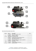
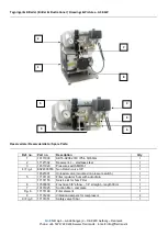
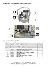
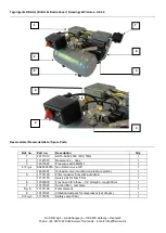
Page 14: ...AIRMO ApS Lundeborgvej 3 DK 9220 Aalborg Denmark Phone 45 53717220 Web www flairmo dk E mail info flairmo dk Tegninger Billeder Bilder illustrationer Drawings Pictures Fig 1 Fig 2 Fig 3 Fig 4 Fig 5 Fig 6 ...

Page 15: ...compressor and a replacement filter element with gaskets pnr 17131153 for the outlet filter Intake filter Outlet filter Dismount the top of the filter housing Push Turn Pull Replace the white filter element Dismount the filter bowl by turning it counterclockwise Pull the bowl straight down Ensure that the O ring comes out along with the bowl DO NOT remove the white auto drain part at the bottom of...

Page 16: ...or leaks and check the pumping time x Clean unit or wipe with a soft damp cloth If necessary use paraffin on rag to remove sticky adhesions Dust and dirt prevent cooling x Check intake filter Clean or replace if necessary Min annually or every 2000 hours whichever comes first x Check the O ring in the non return valve and replace if necessary Note Empty receiver of air before dismounting x Check f...

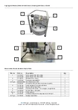
Page 17: ...0Hz 1 2 11121516 Receiver 4 L Grey 1 3 14511029 Pressure switch MDR 1 1 4 Fig 4 E024000359 Non Return valve 3 8 1 14521007 Unloader valve mounted on pressure switch 1 5 17131100 Filter regulator 5 um with auto drain 1 17131153 Service kit for 5um Filter 1 6 17503030 Flex hose 3 8 elbow 1 4 straight length 33cm 1 7 10131025 Suction filter complete 1 Fig 6 17131198 Filter element 1 8 17132016 Vibrat...

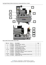
Page 18: ... 2 11121502 Receiver 4 L stainless steel 1 3 14511029 Pressure switch MDR 1 1 4 Fig 4 E024000359 Non Return valve 3 8 1 14521007 Unloader valve mounted on pressure switch 1 5 17131100 Filter regulator 5 um with auto drain 1 17131153 Service kit for 5um Filter 1 6 17503030 Flex hose 3 8 elbow 1 4 straight length 33cm 1 7 10131025 Suction filter complete 1 Fig 6 17131198 Filter element 1 8 17131200 ...

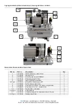
Page 19: ... 2 11121513 Receiver 24 L Grey 1 3 14511012 Pressure switch MDR 2 1 4 Fig 4 E024000359 Non Return valve 3 8 1 14521007 Unloader valve mounted on pressure switch 1 5 17131100 Filter regulator 5 um with auto drain 1 17131153 Service kit for 5um Filter 1 6 17503030 Flex hose 3 8 elbow 1 4 straight length 33cm 1 7 10131025 Suction filter complete 1 Fig 6 17131198 Filter element 1 8 10131021 Vibration ...

Page 20: ...11121513 Receiver 4 L Grey 1 3 14511029 Pressure switch MDR 1 1 4 Fig 4 E024000359 Non Return valve 3 8 1 14521007 Unloader valve mounted on pressure switch 1 5 17131100 Filter regulator 5 um with auto drain 1 17131153 Service kit for 5um Filter 1 6 17503030 Flex hose 3 8 elbow 1 4 straight length 33cm 1 7 10131025 Suction filter complete 1 Fig 6 17131198 Filter element 1 8 10131021 Vibration damp...

Page 21: ...115V IP20 60Hz 2 11121513 Receiver 24 L Grey 1 3 14511029 Pressure switch MDR 1 1 4 Fig 4 E024000359 Non Return valve 3 8 1 14521007 Unloader valve mounted on pressure switch 1 5 17131100 Filter regulator 5 um with auto drain 1 17131153 Service kit for 5um Filter 1 6 17503030 Flex hose 3 8 elbow 1 4 straight length 33cm 1 7 10131025 Suction filter complete 1 Fig 6 17131198 Filter element 1 8 10131...

Page 22: ...2 11121528 Receiver 25 L 1 3 17701042 Kit with pressure switch MDR 1 1 4 17131104 Pressure gauge 0 10 bar 1 5 14521010 AEV1 S pressure unloader 1 6 Fig 4 17701043 Kit with Non Return valve 3 8 1 7 17701045 Kit for receiver auto drain 1 8 17501250 Flex hose 1 4 elbow 1 4 elbow length 50cm 1 9 10131025 Suction filter complete 1 9 Fig 6 17131198 Filter element 1 10 10131039 Vibration dampers for comp...

Page 23: ...L 1 3 17701042 Kit with pressure switch MDR 1 1 4 17131104 Pressure gauge 0 10 bar 1 5 14521010 AEV1 S pressure unloader 1 6 Fig 4 17701043 Kit with Non Return valve 3 8 1 7 17701045 Kit for receiver auto drain 1 8 17501250 Flex hose 1 4 elbow 1 4 elbow length 50cm 1 9 17504020 Flex hose 1 4 x 1 4 length 20 cm 1 10 10131025 Suction filter complete 2 10 Fig 6 17131198 Filter element 2 11 10131039 V...

Page 24: ...FLAIRMO ApS Lundeborgvej 3 DK 9220 Aalborg Denmark Phone 45 53717220 Web www flairmo dk E mail info flairmo dk Manual no 40101016_r02 ...

Reviews: