background image

20

6/

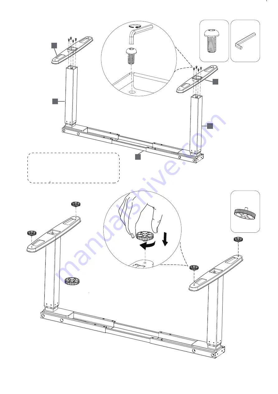
3.

4.

×4

G

A

×4

×4

NOTE

Please tighten screws. 

NOTE

Please tighten screws. 

41

x6

M

M4

M4

G

A

×4

41

x6

M

2

1

2

1

2

2

20

7/

61

x8

M

5.

6.

×8

×4

G

M5

H

×4

B

×8

Please do not fully tighten screws 

until all screws are in place.

2

4

4

2

1

NOTE

20

12/

×2

×2

C

×2

I

×1

D

×2

J

×1

NOTE

Please do not fully tighten screws 

until all screws are in place.

NOTE

Part H can be installed at any 

position as your desired.

I can be installed

NOTE

Please fully tighten screws 

after all screws are in place.

Control box

Memory controller

M 1 2

3 4

> <

20

13/

15.

K

×1

M

1

2

3

4

>

<

AC2-AA3_English V01拼  自翻版

20

8/

7.

8.

×6

×8

F

×6

G

M4

A

×8

NOTE

Please do not fully tighten screws 

until all screws are in place.

41

x6

M

3

3

1

3

3

2

2

4

4

20

11/

11.

12.

×2

×3

C

×3

C

×2

NOTE

Please do not fully tighten screws 

until all screws are in place.

NOTE

Please do not fully tighten screws 

until all screws are in place.

F

×2

F

×3

20

9/

9.

×3

C

×3

NOTE

Shorten the distance between 

the two legs.

NOTE

As shown in this instruction, using desktop,the bottom of

 desktop has installed the embedded nuts in four key

 hole positions. 

NOTE

Please do not fully tighten screws 

until all screws are in place.

F

×3

20

10/

10.

OVERLAP

OVERLAP

AC2-AA3_English V01拼  自翻版

Summary of Contents for Sierra Pro

Page 1: ...Fitnest Sierra Pro Assembly instructions User manual ...

Page 2: ... seconds the display show C and switched the d The display stopped flashing and the switch is complete 3 Switch the unit between CM and Inch unit to CM Pressthe the display show E and switched the unit to inch height then press M followed by a number 1 4 Press the DOWN button on the memory controller until the frame reaches its lowest position Measure the height of the frame from the floor and if ...

Page 3: ...Do not place any objects taller than 20 underneath the desk 5 Do not open any of the components the legs control box or switch 6 Make sure that the power supply is between 110v and 240v before plugging the 7 This product is designed with a duty cycle of 10 2 min on 18 min off 8 Under no circumstances does the manufacturer accept warranty claims or liability IMPORTANT Please read this manual carefu...

Page 4: ...e individual parts must be connected before the control box is connected to 6 During operation If the control box makes unusual noises or smells switch off the main power Take care that the cables are not damaged Unplug the main power cable on mobile equipment before it is moved memory controller There is a risk of injury and electric shock physical or mental abilities can t use the product Unless...

Page 5: ...20 4 EXPLODED DRAWING 1 3 3 2 4 4 2 PARTS 4 K I 1 J 1 Control box Memory controller M 1 2 3 4 L 1 A 18 B 9 C 10 4 4 1 x 6 M 6 1 x 8 M E F 10 M4 G M5 ST4 8x19 D 3 ST3 5x19 H 10 M 6 x 20 _ 2 ...

Page 6: ...20 5 1 2 F 2 2 8 G 180 NOTE Please loosen the screws NOTE Please expand both sides until the hole is exposed M4 1 1 1 1 20 13 15 K 1 M 1 2 3 4 ...

Page 7: ...20 6 3 4 4 G A 4 4 NOTE Please tighten screws NOTE Please tighten screws 4 1 x 6 M M4 M4 G A 4 4 1 x 6 M 2 1 2 1 2 2 ...

Page 8: ...do not fully tighten screws until all screws are in place 2 4 4 2 1 NOTE 20 11 11 12 2 3 C 3 C 2 NOTE Please do not fully tighten screws until all screws are in place NOTE Please do not fully tighten screws until all screws are in place F 2 F 3 ...

Page 9: ...20 8 7 8 8 G M4 A 8 NOTE Please do not fully tighten screws until all screws are in place 4 1 x 6 M 1 3 3 2 2 4 4 ...

Page 10: ...in four key hole positions NOTE Please do not fully tighten screws until all screws are in place F 3 20 9 9 3 C 3 NOTE Shorten the distance between the two legs NOTE As shown in this instruction using desktop the bottom of desktop has installed the embedded nuts in four key hole positions NOTE Please do not fully tighten screws until all screws are in place F 3 ...

Page 11: ...20 10 10 OVERLAP OVERLAP ...

Page 12: ... fully tighten screws until all screws are in place NOTE Please do not fully tighten screws until all screws are in place F 2 F 3 20 7 6 1 x 8 M 5 6 8 4 G M5 H B 8 Please do not fully tighten screws until all screws are in place 2 4 4 2 1 NOTE ...

Page 13: ...screws until all screws are in place NOTE Part H can be installed at any position as your desired Part I can be installed at any position as your desired NOTE Please fully tighten screws after all screws are in place NOTE Control box Memory controller M 1 2 3 4 e9 x2 ...

Page 14: ...20 13 15 L 1 M 1 2 3 4 20 5 1 2 F 2 2 8 G 180 NOTE Please loosen the screws NOTE Please expand both sides until the hole is exposed M4 1 1 1 1 ...

Page 15: ...16 20 14 M 1 2 3 4 ...

Page 16: ...e individual parts must be connected before the control box is connected to 6 During operation If the control box makes unusual noises or smells switch off the main power Take care that the cables are not damaged Unplug the main power cable on mobile equipment before it is moved memory controller There is a risk of injury and electric shock physical or mental abilities can t use the product Unless...

Page 17: ...ight the display will show the desktop height and at the same time until the desk reaches its lowest height and the system will make a sound of beep reset is complete a Press the and at the same time for 3 seconds until the display shows RES and the system will make a sound beep reset is complete b If the Position of desktop is not at the lowest height Please press the IMPORTANT You must reset the...

Page 18: ... seconds the display show C and switched the d The display stopped flashing and the switch is complete 3 Switch the unit between CM and Inch unit to CM Pressthe the display show E and switched the unit to inch height then press M followed by a number 1 4 Press the DOWN button on the memory controller until the frame reaches its lowest position Measure the height of the frame from the floor and if ...

Page 19: ...o anti collision function See below to set anti collision function strength rating Press M and 2 at the same time for 3 seconds and digital controller displays then press 2 it displays L2 the strength rating of L2 is set waiting the controller shows height the setting is completed The same operation set L3 L4 L1 5 Anti collision strength rating setting a Press and hold the DOWN button about 5 seco...

Page 20: ...reset procedure outlined in the Digital Memory Controller section better to hold for 18 minutes Leg 2 has overload over current protection Remove everything from the desktop and perform the reset procedure outlined in the Digital Memory Controller section better to hold for 18 minutes Leg 1 has collided and rebounded The desk will automatically stop and bounce back 2 cm Perform the reset procedure...

Page 21: ......

Reviews: