Fisher Vee-Ball V150 Instruction Manual Download Page 3

14 through 20-Inch Design V150 and V300

3

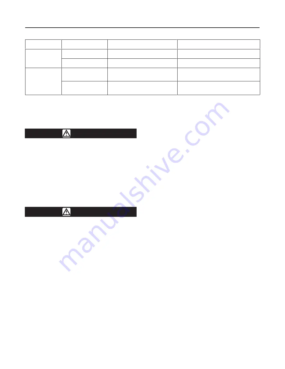
Table 3. Valve Sizes, End Connection Styles, and Ratings

VALVE BODY

MATERIAL

FLANGE COMPATIBILITY

RATING

FACE-TO-FACE DIMENSION

WCC steel

ANSI Class 150 (V150)
raised-face

ASME/ANSI B16.34-1988 Class 150

14 and 16-Inch Valves: ASME B16.10 Short

20-Inch Valves: 20 inches (508 mm)

WCC steel
(standard)

ANSI Class 300 (V300)
raised-face

ASME/ANSI B16.34-1988 Class 300

14-inch Valves: 15 inches (381 mm)
16-inch Valves: 16 inches (406 mm)

CG8M (317 SST)

ANSI Class 150 (V150)
raised-face

See tables in Bulletin 51.3:V150 for
maximum inlet pressure and
temperature

14 and 16-Inch Valves: ASME B16.10 Short

20-Inch Valves: 20 inches (508 mm)

CG8M (317 SST)

ANSI Class 300 (V300)
raised-face

See tables in Bulletin 51.3:V300 for
maximum inlet pressure and
temperature

14-inch Valves: 15 inches (381 mm)
16-inch Valves: 16 inches (406 mm)

Key numbers are shown in figure 9, unless otherwise
indicated.

WARNING

Personal injury or equipment damage
caused by sudden release of pressure
may result if the valve assembly is
installed where service conditions could
exceed either the valve body rating or
the mating pipe flange joint rating. To
avoid such injury or damage, provide a
relief valve for overpressure protection
as required by government or accepted
industry codes and good engineering
practices.

CAUTION

When ordered, the valve configuration
and construction materials were se-
lected to meet particular pressure, tem-
perature, pressure drop, and controlled
fluid conditions. Because some valve/
trim material combinations are limited in
their pressure drop and temperature
ranges, do not apply any other condi-
tions to the valve without first contact-
ing your Fisher Controls sales office or
sales representative.

1.  If the valve is to be stored before installation, pro-
tect the flange mating surfaces and keep the valve
cavity dry and free of foreign material.

2.  Install a three-valve bypass around the control
valve assembly if continuous operation will be neces-
sary during inspection and maintenance of the valve.

3.  Mounting the Actuator:

a.  The valve is normally shipped as part of a con-
trol valve assembly, with the actuator mounted on

the valve. The factory makes actuator/valve adjust-
ments before the valve is shipped.

b.  If the valve and actuator have been purchased
separately or if the actuator has been removed,
mount the actuator according to the 

Actuator

Mounting instructions in the Maintenance section of
this manual.

4.  Be certain the valve and adjacent pipelines are free
of any foreign material that could damage the valve
seating surfaces.

5.  Be sure the mating line flanges are aligned. Pro-
vide standard flat sheet flange gaskets (or spiral
wound gaskets with compression-controlling centering
rings) that are compatible with the process fluid.

Refer to figure 2 for required clearance for valve instal-
lation and stud length. Lubricate the studs with Never-
Seez Pure Nickel Special or an equivalent lubricant.

6.  Install the valve using studs and nuts to connect
the valve flanges to the pipeline flanges. The seal pro-
tector ring (key 3) end of the valve requires longer line
flange studs than standard (see figure 2). Do not at-
tempt to use standard-length line flange studs for the
seal protector end of the valve. Refer to figure 2 for
length of flange studs required.

Install all remaining studs. Tighten the nuts in a criss-
cross sequence to ensure the flange gaskets are prop-
erly loaded.

Note

The valve drive shaft is not necessarily
grounded when installed in a pipeline.
Personal injury or property damage
could result—if the process fluid or the
atmosphere around the valve is flam-
mable—from an explosion caused by a
discharge of static electricity from the
valve components. If the valve is
installed in a hazardous area, electrical-
ly bond the drive shaft to the valve body
(see figure 4).

Summary of Contents for Vee-Ball V150

Page 1: ...VIRO SEALt packing see the Fisher Controls instruction manual titled ENVIRO SEAL Packing System for V Line and ediscR Rotary Valves Refer to separate manuals for information concerning the ac tuator p...

Page 2: ...C Flow Ring with Graphite Ribbon Packing 325 to 1000 F 198 to 538 C PEEK PTFE Bearings 50 to 500 F 46 to 260 C Flow Characteristic Approximately equal percentage Standard Flow Direction Forward into...

Page 3: ...s and keep the valve cavity dry and free of foreign material 2 Install a three valve bypass around the control valve assembly if continuous operation will be neces sary during inspection and maintenan...

Page 4: ...er actuator install a bypass valve on the power actuator if one is not supplied for use during manual operation WARNING Personal injury could result from pack ing leakage Valve packing was tight ened...

Page 5: ...not recommended that the actuator be removed from the valve while the valve is still in the pipeline or between flanges Valve actuator adjustments must be made with the valve out of the pipeline Disa...

Page 6: ...using the parts se quence shown in figure 3 2 Insert the packing follower and packing flange keys 17 and 40 and secure them with the packing follower nuts key 20 Tighten the nuts far enough to stop l...

Page 7: ...14 through 20 Inch Design V150 and V300 7 Figure3 Packing Arrangements A6063 IL 42B8445 B B2412 IL...

Page 8: ...se all pressure from the actuator 2 Remove line bolting remove the control valve ac tuator assembly from the pipeline and place the valve on a protected flat surface with the seal protector ring facin...

Page 9: ...ctor ring making sure the open side of the radial seal faces away from the ball Install the wave spring key 13 on the seal protec tor ring key 3 Install the HD metal seal key 11 into the seal pro tect...

Page 10: ...of the ball it should rotate so the contoured sealing surface of the ball is resting on the surface 4 Remove the flange nuts key 47 the bottom flange key 44 and gasket key 45 from the valve Use a hois...

Page 11: ...0 and into the drive shaft splined ear of the the V notch ball Note 1 See note 1 figure 9 2 For valves with metal bearings hold the thrust washer key 38 figure 9 in place before inserting the drive sh...

Page 12: ...res to install the ball seal and seal protector ring Actuator Mounting Standard flow direction is with the seal protector ring key 3 figure 9 facing upstream Install the valve with the drive shaft hor...

Page 13: ...14 through 20 Inch Design V150 and V300 13 Figure 7 Index Mark for Actuator Lever Orientation 43B5324 B C0768 1 IL...

Page 14: ...linkage until the open position is obtained using the appropriate actuator instruction manual procedures 3 Stroke the valve to the closed position Make sure the actuator does not stroke the ball more...

Page 15: ...umber 16 Packing Set Set includes PTFE V ring packing with one carbon filled conductive ring Male adapter and female adapter 14 inch 12A9057X022 16 inch 1R5162X0012 20 inch 1R6699X0012 17 Packing Foll...

Page 16: ...14 through 20 Inch Design V150 and V300 16 Figure 9 Design V150 and V300 Valve Assembly 43B7128 A DOC 43B6886 A DOC...

Page 17: ...1K242935222 16 inch 1R284835222 20 inch 1P323635222 V300 Steel 14 inch 1A378131012 16 inch 1A378131012 S31600 Stained Hardened 14 inch 1A378135222 16 inch 1A378135222 Key Description Part Number 47 He...

Page 18: ...12 43B6886X032 16 43B0683X022 43B0683X012 43B0683X032 20 43B6050X022 42B6050X012 43B6050X032 Left Hand Mounted Actuator 14 43B8054X022 43B8054X012 43B8954X032 16 43B7123X022 43B7123X012 42B7123X032 20...

Page 19: ...X012 13B7124X022 13B7125X012 20 14B3655X012 14A6555X012 14A6556X012 14A6542X012 1 PEEK stands for poly ether ether ketone Key 11 Ball Seal VALVE SIZE INCHES COMPOSITION FORWARD FLOW ONLY HEAVY DUTY ME...

Page 20: ...al Inc 1987 1995 All Rights Reserved This product may be covered under one or more of the following patents 5 129 625 5 131 666 5 056 757 5 230 498 and 5 299 812 or under pending patent ENVIRO SEAL ed...

Reviews: