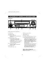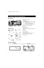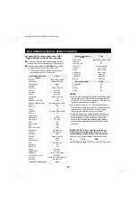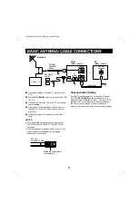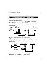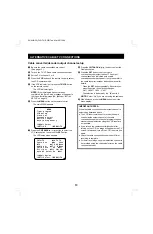
LOCATIONS OF CONTROLS AND INDICATORS
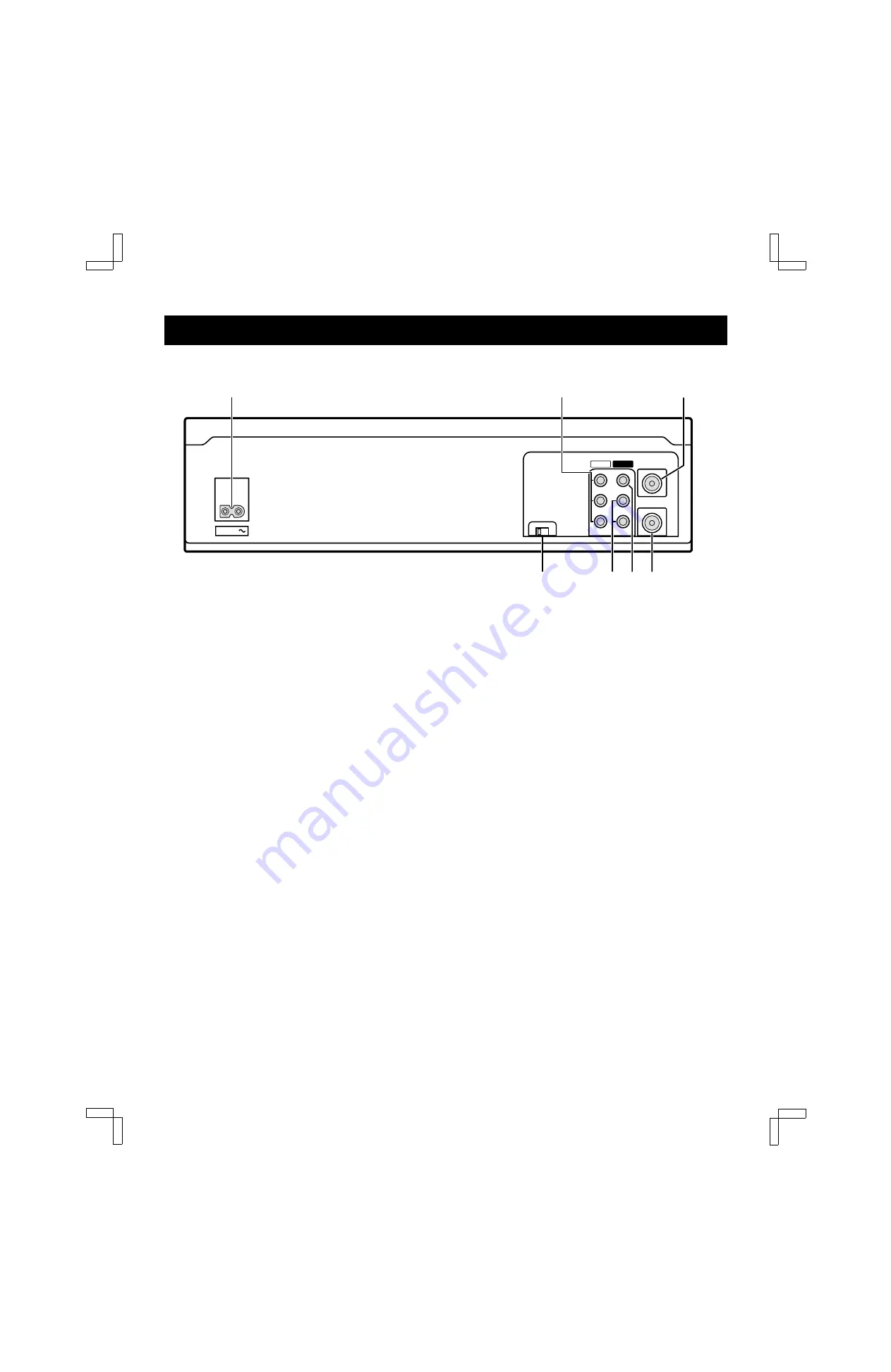
Back Panel
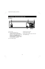
1
AC power input
2
Rear-panel AUDIO/VIDEO input jacks
Connect the audio and video outputs from an
external unit (i.e. a video camera, second VCR) to
these jacks. To record the signals coming from the
external unit, press the INPUT button on the
remote control to display “L1” instead of a channel
number (see page 25). If only one audio jack is to
be used, connect it to the L (left) jack.
3
VHF/UHF antenna input jack
4
VHF/UHF antenna output jack
5
VIDEO output jack (yellow)
6
AUDIO output jacks (Red for right and white for left)
7
RF CHANNEL switch
RF
CHANNEL
3
4
VIDEO
AUDIO
VHF/UHF
FROM ANT.
TO TV
OUT
IN
IN
OUT
L
R
AC IN
5
6
2
7
1
3
4
SU4H/UF2 (FVH-T619 GB) Tue. Mar. 09/1999
7


