


R32 ATW Service Manual
40
after completion.
3) The outdoor unit cannot be connected when holding pressure.
11.3.7 Vacuum pumping
1) A vacuum pump with a vacuum degree of -0.1μm or less and gas displacement of above 40L/min
shall be used.
2) The outdoor unit does not need to be vacuumed. Do not open the shut-off valve on the gas side or
liquid side of the outdoor unit.
3) Confirm that the vacuum pump can work below -0.1MPa after running for more than 1 hour. If it
cannot work below -0.1MPa after running for more than 2 hours, it indicates that there is moisture or
gas leakage inside and needs to be checked.
4) The vacuum pump must be equipped with a check valve.
11.3.8 Adding amount of refrigerant
The calculation method of the adding amount of refrigerant is shown in the following table, based on
the pipe diameter and length of connection liquid side piping between outdoor unit and the hydronic
module.
Liquid pipe diameter (mm)
Pipe length (m)
Adding amount of refrigerant (kg)
φ9.52
≤
5
φ9.52
>5
Add 0.03kg for each additional 1m
Note: R32 refrigerant must be charged in liquid form with fixed amount measured by electronic scale.
11.3.9 Instructions for use of the shut-off valve
1) It shall be in OFF state when delivery.
2) Open or close the valve with a 6 mm hex wrench, counterclockwise turning for opening and
clockwise turning for closing.
3) The valve cover must be tightened after the operation.
4) The operation of vacuuming and refrigerant injection at the service port must be operated with the
special tool R32. Inject the refrigerant at the gas side valve service port, and vacuum at the liquid side
and the gas side valve service port.
Attention
Do not mix tools and measuring instruments used for different refrigerants and in direct contact
with the refrigerant.
Never remove air with refrigerant gas.
When the vacuum degree cannot reach -0.1MPa, please consider whether there is a possibility of
leakage. Please
confirm again if there is any leakage. If there is no leak, run the vacuum
pump for one or two more hours.
Summary of Contents for FHIF-WHS-120CE3
Page 2: ......
Page 9: ...R32 ATW Service Manual 7 1 2 2 Hydronic module FHIF WHS 120CE3 FHIF WHS 160CE3...
Page 18: ...R32 ATW Service Manual 16 Pic 4 3 Domestic hot water mode operation range...
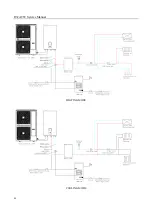
Page 23: ...R32 ATW Service Manual 21 8 System diagram...
Page 28: ...R32 ATW Service Manual 26 Main PCB 3 Hydronic module Main PCB...
Page 29: ...R32 ATW Service Manual 27 Filter board...
Page 34: ...R32 ATW Service Manual 32 Model FHOF WHS 160CE3 3F...
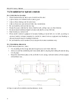
Page 35: ...R32 ATW Service Manual 33 Single unit installation More than one unit installation Unit mm...
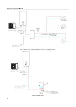
Page 46: ...R32 ATW Service Manual 44 HEATING MODE COOLING MODE...
Page 47: ...R32 ATW Service Manual 45 HEATING MODE WITHOUT COOLING MODE DHW MODE WITHOUT COOLING MODE...
Page 48: ...R32 ATW Service Manual 46 HEATING MODE WITHOUT DHW MODE AND DHW TANK ONLY DHW MODE...
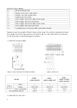
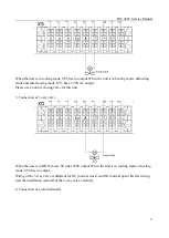
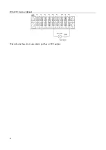
Page 56: ...R32 ATW Service Manual 54 When the unit has error code alarm port has a 220V output...
Page 59: ...R32 ATW Service Manual 57...


