20
INSTALLATION INSTRUCTIONS
Cabinet mounting installation
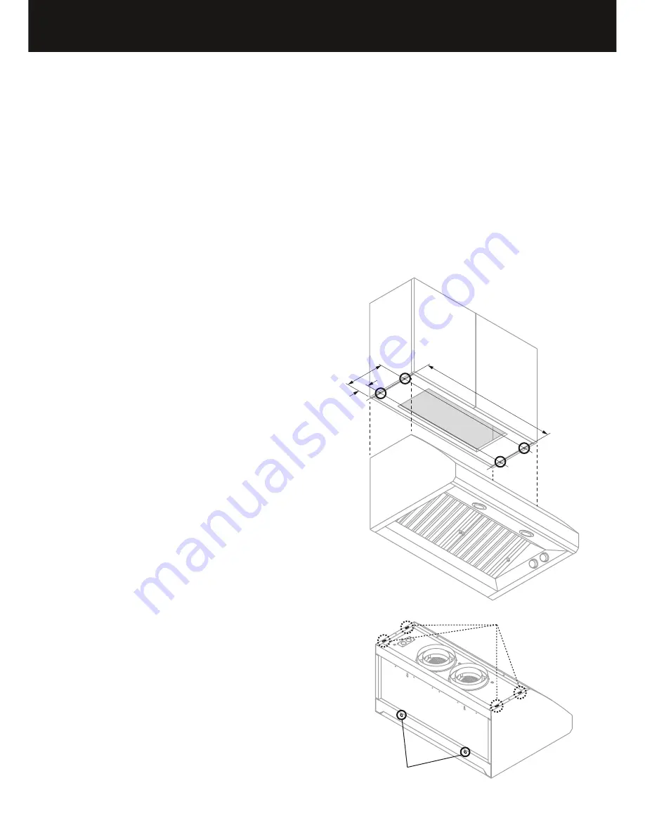
The range hood can be installed under a cabinet by supporting the range hood from the
top. For cabinet mounting installation the transition should be mounted after installing
the range hood, see ‘Duct transition assembly’ and ‘Product dimensions’ sections. If
the transition is used allowance needs to be made in the cabinetry back wall for easier
ducting attachment and sealing.
WARNING!
The cabinet must be of sufficient strength and structurally joined to the wall studs to
support the weight of this range hood.
IMPORTANT!
It is recommended that the cabinet has a door or service panel that can be easily
opened to access the power connection box.
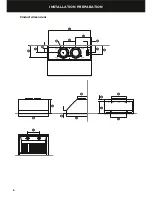
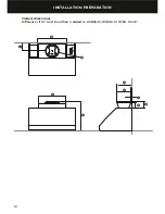
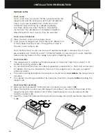
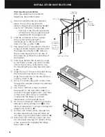
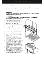
1
To determine the location for the four
screws that will secure the range hood to
the cabinet, refer to ‘Product dimensions’ for
measurements of
L
,
M
and
N
.
2
Draw a line to mark distance
L
along the
underside of your cabinet.
3
At either end of
L
, draw two lines, one at
distance
M
from the wall, the other one at
distance
N
from the wall. This will give you
the 4 positions for the screw holes.
Note: Allow space for the power conduit, and
ducting attachment in the cabinetry base.
4
In the base of the cabinet, drill 1/8” (3mm)
holes as marked.
5
Screw four 3/4” (19mm) screws leaving 1/4”
(6mm) of the screw exposed to hang the
range hood on.
6
Using two people lift and hang the range
hood from the screws through keyslots
provided on range hood top (refer to
I
).
Tighten the four screws.
7
Drill a 3/8” (9.5mm) hole through the center
of the holes indicated in
H
into the wall.
Insert two wall plug into the drilled holes.
Tighten the range hood to the wall plugs
by installing the 3/4” (19mm) washers onto
the screws supplied with the wall plug, then
tightening.
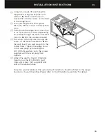
8
If using a optional duct transition, attach
the 10” (254mm) transition now, see ‘Duct
transition assembly’ section for details.
9
Attach the duct to the 10” (254mm) transition
or 8” (203mm) duct rings with screws (not
supplied) and seal with aluminum tape.
M
N
L
H
I
Summary of Contents for HC36 Shell
Page 2: ...English Page 1 29 Français Page 31 59 ...
Page 4: ......
Page 10: ...8 INSTALLATION PREPARATION Product dimensions P O Q A B I C D S R K T E F M N G L J H ...
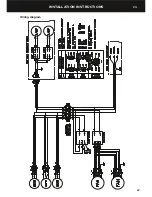
Page 25: ...23 INSTALLATION INSTRUCTIONS Wiring diagram EN ...
Page 32: ......
Page 34: ......
Page 55: ...53 Schéma de câblage INSTRUCTIONS D INSTALLATION FR ...
Page 62: ......
Page 63: ......


