®
7
8. PILOT START-UP, OPERATIONAL TESTS
Before proceeding with the start-up and operational tests of SP-32-
NG/PG-ND
pilot check the following:
8.1 Gas installation is correctly connected, tight and functionally checked, including: valves, flaps, strainers,
fittings and joints (flanged and screwed) as well as control and interlock devices.
8.2 Gas connection to the pilot
is
made in accordance with the above instructions and the assembly drawing.
8.3 Electrical components and circui
ts
are properly connected, grounded and tested.
8.4 Power supply to the electrical circuit of the ignition device and spark or arc release should be allowed only
after assembly of the device, in the operating position on the burner or outside the burner only to validate the
operation strictly according to the
device instructions e.g. on special test stand.
Then perform next steps:
8.5 Select one pilot as a representative for tests.
8.6 Prepare the burner control system to enable manual trials in a safe way.
8.7 Install for the trial period appropriate gauge and manual valve on the pilot gas supply line. This will allow
for fine adjustment of the gas pressure.
8.8 After verification of ignition device mounting and wiring, the electric igniter can be powered up. Check for
the spark or arc presence.
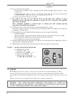
8.9 At presence of a spark or an electric arc from ignition device, slowly open the pilot manual shut-off gas
valve with the air inlets obscured by adjusting
sleeve completely (pos
. 5 on Fig.1). At a certain degree of
opening the pilot flame should establish.
8.10 Adjust the gas pressure slowly up to the working pressure value. Pilot flame may be yellow and bushy due to
too little combustion air.
8.11 Loosen the locking thumb screw and adjust the air sleeve until the flame stabilizes at the air tube end and
reaches blue-yellow color. Each time secure the sleeve position by tightening the screw.
The air tube should not glow
(it starts to glow at 400-500
°C) - if this happens adjust the air and gas or
eventually the main burner air pressure (in the windbox) to stabilize the flame in the desired position and to
stop the glow effect. Flame should be as stable as possible.
Remarks:
a) Pilot flame should be blue near the igniter tip and yellow at its end. With some kind of gases the
flame color may stay yellow.
b) In some applications e.g. on up-fired burners, when the draught of the furnace is significant, it may
be necessary to limit the amount of air by obscuring air inlets accordingly in order to keep stable
pilot flame, bearing in mind, that air adjustment possibility of natural draught pilot
is
limited.
c) A gas pilot, after correct adjustments, should ignite reliably and burn with a stable flame at each
selected gas pressure point throughout his operational pressure range. However, it should be noted
that, the pilot is not intended to be used as a burner - its turn-down ratio is typically 1:1.
8.12 In case of insufficient pilot capacity, the amount of gas and air can be further adjusted bearing in mind the
above principles.
8.13 In multiple burner and pilot applications on one heater/boiler with a similar gas supply installation and
similar layout on the main burner, set the other pilot
’
s gas manual valve and the air adjusting sleeve to the
same position.
8.14 Then carry out light-off tests. In case of differences in the quality of combustion adjust gas manual valve and
air sleeve so that the flame is similar to that on the test pilot. In some cases the main burner air should be
adjusted.
8.15 Repeat the light-off tests several times on each pilot to confirm the repeatability of ignition. Flame should be
stable, in correct position and of desired shape.
8.16 For outdoor installation, pay attention to the influence of wind strength and direction on the quality of the
pilot flame. In the event of its significant impact appropriate measures should be taken, e.g. in the form of
fences around the burners or heater limiting this influence.
If the
SP-32-
NG/PG-
ND
gas pilot has been correctly commissioned and the settings were optimized, with correct
maintenance, the igniter will operate trouble free.

