62
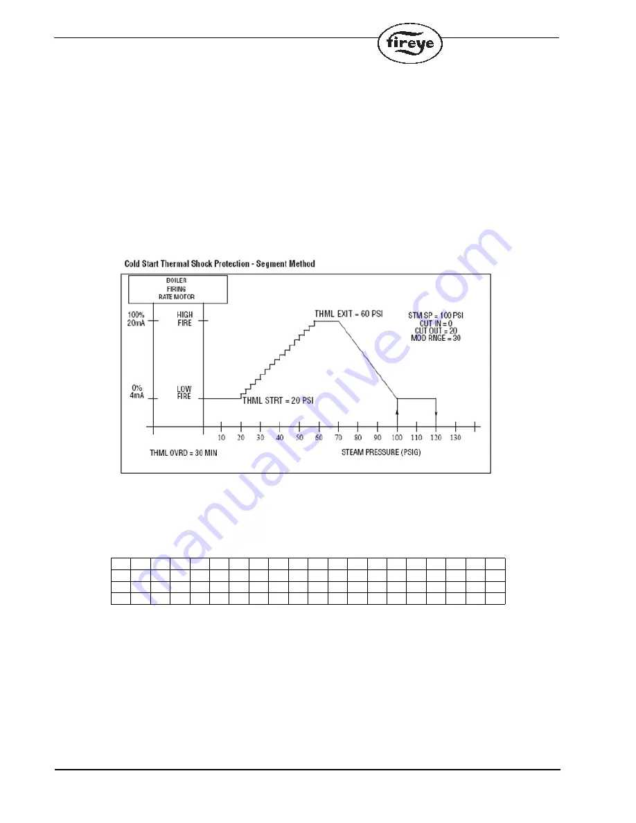
of one segment and repeats the process. The PPC4000 steps the firing rate until the steam pressure
(or water temperature) reaches the Thermal Shock Exit Point (
THERMAL EXIT
). At that point, the
firing rate is at the high fire position, and will remain at the high fire position until the steam pressure
(or water temperature) breaks into the proportional band.
NOTE:
1. If the sensor being used for thermal shock is the same type as the PCV sensor (steam or water) the
Thermal Shock Exit value cannot be greater than the PCV setpoint.
TIMED OVERRIDE:
The Timed Override Per Segment Setpoint (
THERMAL OVERRIDE
)
allows the user to program a maximum time period, 0 to 30 minutes, in which the control will wait
before forcing an increase in firing rate to the next segment position. If the steam pressure (or water
temperature) DOES NOT increase to the appropriate value, the PPC4000 will automatically advance
the firing rate position to the next segment position.
COMMUNICATIONS SETUP
The communications setup is needed to configure the PPC4000 to effectively perform Modbus and
sequencing communications. Communication setup can be accessed from the top menu screen and
the underlying setup screen is shown below:
The baud-rate and unit address is configurable in the communication setup screen. The selections for
baud-rates are: 57600 (default), 38400, 19200, 9600, 4800. In order for Modbus master and slave to
communicate effectively, the baud-rate must be set to be identical at the master and the slave.
The selection for unit addresses are: 1 through 247, where 247 is default. It should be noted that an
address conflict in the sequencing chain or Modbus chain will result in communication lockup,
whereby devices with address conflict cannot effectively communicate. So, it is important that the
addresses are unique on all communication devices.
<
C
O
M
M
U
N
I
C
A
T
I
O
N
S
E
T
U
P
B
A
U
D
R
A
T
E
5
7
6
0
0
U
N
I
T
A
D
D
R
E
S
S
2
4
7


