4
INSTALLATION
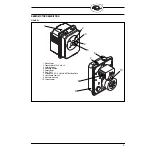
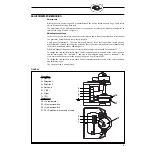
FIGURE 2.
MECHANICAL MOUNTING
Fasten the NX20 servo motor using four M6 metric bolts through a suitable mounting into the
threaded holes (1) using spigot (2) for location so that the mounting surface (4) rests flat. The depth
of the threaded holes (1) is 13mm
The output drive shaft (3) should be connected using a suitable arm, link or flexible coupling.
The mounting position of the NX20 servo motor is arbitrary.
Electrical installation
Loosen the four cross-head housing cover screws and pull the cover hard to remove it.
For the electrical installation of the NX20 servo motor, use the prescribed cable type (corresponding
to the environmental conditions).
Prepare the power supply, potentiometer, protective earth and control cables by suitably removing
sheaths and insulation.
Feed cables through screwed cable entry via suitable conduit and glands and place the stripped ends
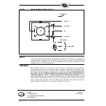
of the leads into screw connection terminals and terminate as shown in the wiring diagram Figure 3.
Ensure that no bare wires protrude from the terminals and thus produce the risk of a current surge or
of a short circuit.
Store the cables such that they are not pinched when the housing cover is fitted or interfere with the
end travel switch cam mechanism or potentiometer coupling shaft.
In the case of a servo motor which is open and ready to operate there is the risk that live parts may be
touched and a shock received.
Switch on the power supply and check that the servo motor drives correctly.
Next carry out the adjustments/commissioning or otherwise replace the housing cover.
1
2 3
4


