32
OD42 Outdoor Gas Fireplace
MAINTENANCE
DIGITAL FIREPLACE BURNER CONTROL REMOVAL
5.
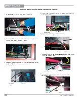
Disconnect the Black sparker wire with black spade connector from CN3.
See Diagram 2 below.
6.
Disconnect the white and green On/Off switch wires.
See Diagram 3 below.
7.
Disconnect the yellow ground wire with green diagonal stripe for pilot
(CN2). See Diagram 4 below.
8.
Disconnect the three valve wires (yellow wire with green stripe).
See Diagram 5 below.
Diagram 1
Diagram 5
Diagram 2
Diagram 3
Green
White
Diagram 4
Pilot Sensor
Wire
Sparker Wire
ON/OFF wires
Ground wire
Valve wire
2.
Remove the DFC from the fl oor of the fi rebox by removing 2 screws in
locations shown below to release DFC bracket.
4.
Disconnect the Black Pilot sensor wire with Red Spade connector from
the 'ON' on DFBC (
Digital fi replace burner control) box.
See Diagram 1 below.
1
Remove 6 screws in locations shown below to access DFC.
6th screw located at back
Summary of Contents for OD42-N
Page 5: ...OD42 Outdoor Gas Fireplace 5 DIMENSIONS UNIT DIMENSIONS WITH 2 FACEPLATE ...
Page 6: ...6 OD42 Outdoor Gas Fireplace DIMENSIONS UNIT DIMENSIONS WITH 4 FACEPLATE ...
Page 36: ...36 OD42 Outdoor Gas Fireplace NOTES ...
Page 37: ...OD42 Outdoor Gas Fireplace 37 NOTES ...


