background image

24

OD42 Outdoor Gas Fireplace

INSTALLATION

FACEPLATE INSTALLATION

Remove the protective coating from the faceplate before installation - see 
handling instructions in panel install section.

1)


 To install the faceplate - line up the tabs on the faceplate with the  'C' 
shaped openings on the left and right sides of the unit.  There are 3 
slots on each tab so the faceplate to accommodate different fi nishing 
materials. 

2)


Install logo onto faceplate.  

4)


To remove - reverse steps.

3)


 For installations where thicker fi nishing material is used - the optional 
trim piece may be installed to fi ll the gap. 


Install the trim between the bottom access panel and the faceplate as  

 shown 

below.

Trim Piece

Final Install

2)

3)

Summary of Contents for OD42-N

Page 1: ...bor s phone Follow the gas supplier s instructions If you cannot reach your gas supplier call the fire department 919 001e 03 18 14 Owners Installation Manual Tested by Installer Please complete the details on the back cover and leave this manual with the homeowner Homeowner Please keep these instructions for future reference MODELS OD42 N OD42 P Outdoor 42 Gas Fireplace WARNING FOR OUTDOOR USE ON...

Page 2: ...l the warmth and charm of a fire at the flick of a switch The OD42 Outdoor fireplace has been approved by Warnock Hersey Intertek for both safety and efficiency As it also bears our own mark it promises to provide you with economy comfort and security for many trouble free years to follow Please take a moment now to acquaint yourself with these instructions and the many features of your Outdoor Fi...

Page 3: ... 14 880 S I T Valve Description 14 Aeration Adjustment 14 Unit Assembly Prior to Installation 15 Standoff Assembly 15 Nailing Strips 15 Drain Installation Recommended 16 Wall switch installation 17 Battery installation replacement 17 Wiring Diagram 18 Inner panel installation 19 Fireglass installation 20 Twig Set Installation 21 Heat deflector installation 23 Faceplate installation 24 Glass wind s...

Page 4: ...ion minimum Pression à la tubulure d chappement lev e Grandeur de l injecteur D bit maximum selon l altitude Pression d allimentation maximum Calorifique é é é é 14 WC C E 3 49 kPa 11 WC C E 2 74 kPa WC C E 43 500 Btu h 12 74 kW 10 2 49kPa 47 DMS 0 4500 ft pi 0 1372m Minimum supply pressure Manifold pressure high Orifice size Maximum input Altitude Maximum supply pressure D E F A B C Side Walls A ...

Page 5: ...OD42 Outdoor Gas Fireplace 5 DIMENSIONS UNIT DIMENSIONS WITH 2 FACEPLATE ...

Page 6: ...6 OD42 Outdoor Gas Fireplace DIMENSIONS UNIT DIMENSIONS WITH 4 FACEPLATE ...

Page 7: ...BE PLACED ON OR NEAR THE APPLIANCE DO NOT USE THIS APPLIANCE IF ANY PARTHASBEENUNDERWATER IMME DIATELY CALL A QUALIFIED SERVICE TECHNICIAN TO INSPECT THE APPLI ANCE AND TO REPLACE ANY PART OF THE CONTROL SYSTEM AND ANY GAS CONTROL WHICH HAS BEEN UNDER WATER YOUNG CHILDREN SHOULD BE CARE FULLY SUPERVISED WHENTHEY ARE IN THE SAME AREA AS THE APPLI ANCE TODDLERS YOUNG CHILDREN AND OTHERS MAY BE SUSCE...

Page 8: ...asfireplace section b Clearances to Combustibles Refer to Clearances section c Mantel Clearances Refer to Combustible Mantel Clearances section d Framing Finishing Requirements Refer to Framing Finishing section 2 Top Facing Support and Side Nailing Strips Refer to Unit Assembly Prior to Installation Section Note Must be done before installing unit into place 3 Drain Installation 4 Install ON OFF ...

Page 9: ...plus one of remaining walls must have a fixed opening All outdoor fireplaces fire tables require total natural ventilation of 50 open space Correct Working Gas pressure is critical on OD42 units Wherever possible avoid locating on a flat wall in a tight corner Floor space doesn t count as open area Install to the manual specs for framing and do not insulate unit or enclosure Framing enclosure must...

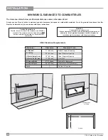
Page 10: ...ES The clearances listed below are Minimum distances unless otherwise stated A major cause of fires is failure to maintain required clearances air space to combustible materials It is of the greatest importance that this fireplace be installed only in accordance with these instructions F E D A C B OD42 Clearance Requirements Clearance Dimension Measured From A Sidewall 11 203mm Side of Fireplace O...

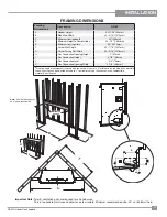
Page 11: ...orner Facing Wall Width 54 3 16 1376mm H Gas Connection Opening Height 2 51mm I Gas Connection Height 3 7 8 98mm J Gas Connection Inset 3 4 73mm K Gas Connection Opening Width 3 7 8 98mm Framing depth measurement is noted with the nailing strips set as far forward on the firebox as possible The nailing strips can be adjusted back up to 1 to allow for varying thicknesses in non combustible material...

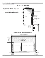
Page 12: ...s used on the mantel and the facingis heatresistant orthepaintmaydiscolour Combustible Material 2 0 12 6 4 8 10 12 305mm Standoff Metal Stud On Edge 0 14 Non combustible Facing To Unit Base 1 25mm 26 1 2 18 23 10 20 26 Top of Fireplace Opening 11 MANTEL CLEARANCES NON COMBUSTIBLE REQUIREMENTS 2 7 8 3mm 6 9 16 167mm 10 7 8 276mm 16 406mm 38 1 16 767mm Non combustible Material Non combustible Materi...

Page 13: ...ning dimensions noted below must be adhered to ensuring for the removal of the faceplate and for the safe operation of this appliance For material such as brick stone etc that extend up to 1 1 2 the minimum opening dimensions noted below must be adhered when finishing around the 2 or 4 faceplate This is to ensure the removal of the faceplate and for the safe operation of this appliance For facing ...

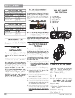
Page 14: ...accordingly 3 Reverse Steps 1 12 HIGH ELEVATION This unit is approved for altitude 0 to 4500 ft CAN1 2 17 M91 GAS LINE INSTALLATION Since some municipalities have additional local codes it is always best to consult with your local authorities and the CAN CGA B149 installation code For USA installations follow local codes and or the current National Fuel Gas Code ANSI Z223 1 When using copper or fl...

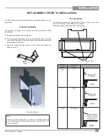
Page 15: ... Remove the standoffs from the fireplace 2 Take each standoff and bend into the correct shape Bend up at the bend lines until the screw holes in the standoff and the pre punched screw holes on the fireplace top line up 3 Attach the standoff securely to the unit with 2 screws per standoff on opposite corners Standoffs installed Nailing Strips Note Depending on the material used for finishing the na...

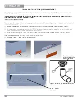
Page 16: ...screws to remove the rear access panel from the back of the unit this will allow access to the drain hole at the base of the unit 2 On the exposed drain hole see location below install a PVC 3 4 threaded coupling reducer going from the top of the pan down through the hole Apply a silicone based sealant around the base and threads before installation 3 Holding the reducer coupling with a wrench thr...

Page 17: ...nstall weather resistance cover plate to switch using 2 inner holes with screws provided Ensure gasket and spacer are in place 6 Mount completed switch assembly with cover plate to the electrical box using 2 outer holes on cover plate Shown without facing material CAUTION Do not wire wall switch wires to 120V wire BATTERY INSTALLATION REPLACEMENT 2 Remove the 2 screws securing the battery compartm...

Page 18: ...umstances NOTE 4 AA batteries must be installed in the battery pack to operate the burner switch Remove the protective coating from the following components before proceeding Carefully follow stainless handling instructions on following page 0 886 001 Proflame Valve Standard Main On Off Switch or Optional Wall Switch SureFire Switch 880 Proflame 880 Standard Wall Switch ...

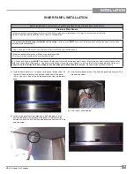
Page 19: ...nd and finger marks MUST be cleaned off with a soft cloth and a stainless steel cleaner Most stainless steel cleaners leave a film residue on the surface of the panels Use an ammonia based cleaner ie glass cleaner to remove this film before applying heat to the unit Failure to do this will result in burn stains on panels which you will be unable to remove Not protected by product warranty 1 Instal...

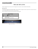
Page 20: ...bags Spread the Fireglass evenly over the burner Ensure the Fireglass does not overlap too much as this will effect the flame pattern IMPORTANT NOTE Only the approved Fireglass is be used with these fireplaces Use of any other type of Fireglass can alter the unit s performance any damage caused by the use of any unapproved glass or stones will not be covered under warranty Ensure the Fireglass doe...

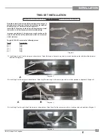
Page 21: ... can alter the unit s performance which is not covered under warranty Twig kit 326 930 contains the following pieces Part Description A x 1 Twig B x 1 Twig C x 1 Twig D x 1 Twig E x 1 Twig Diagram 2 Diagram 1 F E D C B A A C 1 Install twigs A and C on the burner as shown below Orient the twigs in the same way and in a similar location on the left side of the burner as depicted in Diagram 2 2 Insta...

Page 22: ...ross twig E in the same way and in a similar position as depicted in Diagram 5 twig D will rest up against the back panel 5 Install twig F on the right side of the burner as shown below Orient twig F in the same way and in a similar position as depicted in Diagram 6 Diagram 5 Diagram 6 Final Install D E F ...

Page 23: ...OD42 Outdoor Gas Fireplace 23 INSTALLATION HEAT DEFLECTOR INSTALLATION 1 Install the heat deflector to the top inside of the firebox with 4 screws as shown below Heat Deflector Heat Deflector Installed ...

Page 24: ...te with the C shaped openings on the left and right sides of the unit There are 3 slots on each tab so the faceplate to accommodate different finishing materials 2 Install logo onto faceplate 4 To remove reverse steps 3 For installations where thicker finishing material is used the optional trim piece may be installed to fill the gap Install the trim between the bottom access panel and the facepla...

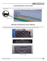
Page 25: ...riods of time The soft fabric cover is made of weather resistant material to protect the unit from the elements Starting from one corner slide the cover over the corner then stretch the cover until it is fitted over all four corners CAUTION Never start the unit with the cover on Let the unit cool before installing the cover Turn off gas supply to unit before installing cover GLASS WIND SHIELD INST...

Page 26: ... 180 apart The openings need to be a total area of 1 in lb 14 2 cm kg of fuel storage capacity 5 Max 5 Max 2 Min 1 Max Bottom opening must provide a minimum of 1 2 square inches 3 23 cm for each pound of pro pane LP contained in the tank see example be low Every opening must have minimum dimensions to allow entrance of a 1 8 3 2mm diameter rod Ventilation openings in side walls must not communi ca...

Page 27: ...ible shock 3 Check to ensure there are no gas leaks 4 Ensure that the stainless panels are installed 5 Verify twig placement If the pilot cannot be seen when lighting the unit the twigs have been incorrectly positioned 6 The unit should never be turned off and on again without a minimum of a 60 second wait LIGHTING PROCEDURE 1 Turn on ON OFF switch 2 After approximately 4 seconds the spark igni ti...

Page 28: ...aide ou des informations supplé mentaires consulter un installateur qualifié une agence de service ou fournisseur de gaz 918 892a s DO NOT REMOVE THIS INSTRUCTION PLATE LIGHTING INSTRUCTIONS STOP Read the safety information on this label 1 Turn off ON OFF switch 2 If service is to be performed you must disconnect power to the unit from the battery pack refer to manual 1 Appuyez sur le bouton ON OF...

Page 29: ... to the unit Failure to do this will result in burn stains on panels which you will be unable to remove 4 The OD42 is finished in a heat resistant paint and should only be refinished with heat resistant paint Firegear Outdoors uses StoveBright Paint Metallic Black 6309 5 Make a periodic check of burner for proper position and condition Visually check the flame of the burner periodically making sur...

Page 30: ...crew and panel clip on the right side Remove the right side panel once the clip has been removed 11 Remove left and right screws from the burner legs 9 Remove the front access panel by lifting up and out 10 Remove the burner tray by lifting up and out 7 Remove the screw and panel clip on the left side Remove the left side panel once the clip has been removed 8 Remove the back panel once the 2 side...

Page 31: ...lift out valve tray 16 Replace with new valve tray and reverse steps Inspect gasket condition replace if necessary 12 Slide the burner to the right and lift up and out of the firebox 13 Remove 6 screws in locations shown below to access DFC 6th screw located at back ...

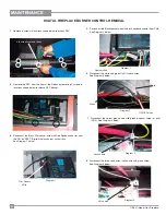
Page 32: ...sconnect the three valve wires yellow wire with green stripe See Diagram 5 below Diagram 1 Diagram 5 Diagram 2 Diagram 3 Green White Diagram 4 Pilot Sensor Wire Sparker Wire ON OFF wires Ground wire Valve wire 2 Remove the DFC from the floor of the firebox by removing 2 screws in locations shown below to release DFC bracket 4 Disconnect the Black Pilot sensor wire with Red Spade connector from the...

Page 33: ...lector 5 904 777 Orifice 29 NG 904 434 Orifice 47 LP 6 326 574 P Valve Assembly NG 326 576 P Valve Assembly LP 326 007 P Front access panel 326 048 Burner Tray Cover Part Not Shown Part Description 10 326 036 Top nailing strip 11 326 037 F Side nailing strip 12 940 368 P Glass Windshield 911 012 DFC Digital Fireplace Control 910 363 Wall Switch 919 001 Manual Part Not Shown ...

Page 34: ... 911 024 Valve NG SIT 880 911 025 Valve LP SIT 880 15 911 006 Pilot Assembly NG 911 007 Pilot Assembly LP 911 039 Pilot Hood 2 way 911 137 Pilot Hood Clip 910 432 Pilot Tube w Nuts 326 054 Perforated Pilot Cover Part Description 904 777 Orifice 29 NG 904 434 Orifice 47 LP 326 930 Driftwood Twig Set Optional Part Not Shown ...

Page 35: ...6 17 18 Part Description 12 940 368 P Glass Wind shield 16 326 021 Rear Enamel Panel 17 326 022 Left Enamel Panel 18 326 023 Right Enamel Panel 19 326 552 2 Faceplate Brushed Stainless 326 937 4 Faceplate Brushed Stainless 946 676 Copper Fireglass Part Not Shown ...

Page 36: ...36 OD42 Outdoor Gas Fireplace NOTES ...

Page 37: ...OD42 Outdoor Gas Fireplace 37 NOTES ...

Page 38: ...38 OD42 Outdoor Gas Fireplace NOTES ...

Page 39: ...vice work carried out on your Firegear Outdoors product Firegear Outdoors will not be liable for results or costs of workmanship from unauthorized service persons or dealers At all times Firegear Outdoors reserves the right to inspect product in the field which is claimed to be defective All claims must be submitted to Firegear Outdoors by authorized selling dealers It is essential that all submit...

Page 40: ...____________________________________ Date Installed ______________________________________________________ Serial No __________________________________________________________ Firegear Outdoors fireplaces are designed with reliability and simplicity in mind In addition our internal Quality Assurance Team carefully inspects each unit thoroughly before it leaves our door See the inside back cover fo...

Reviews: