background image

Page 6 of 8


T

OTAL

P

AC


®

3


Integrated Fire Protection System


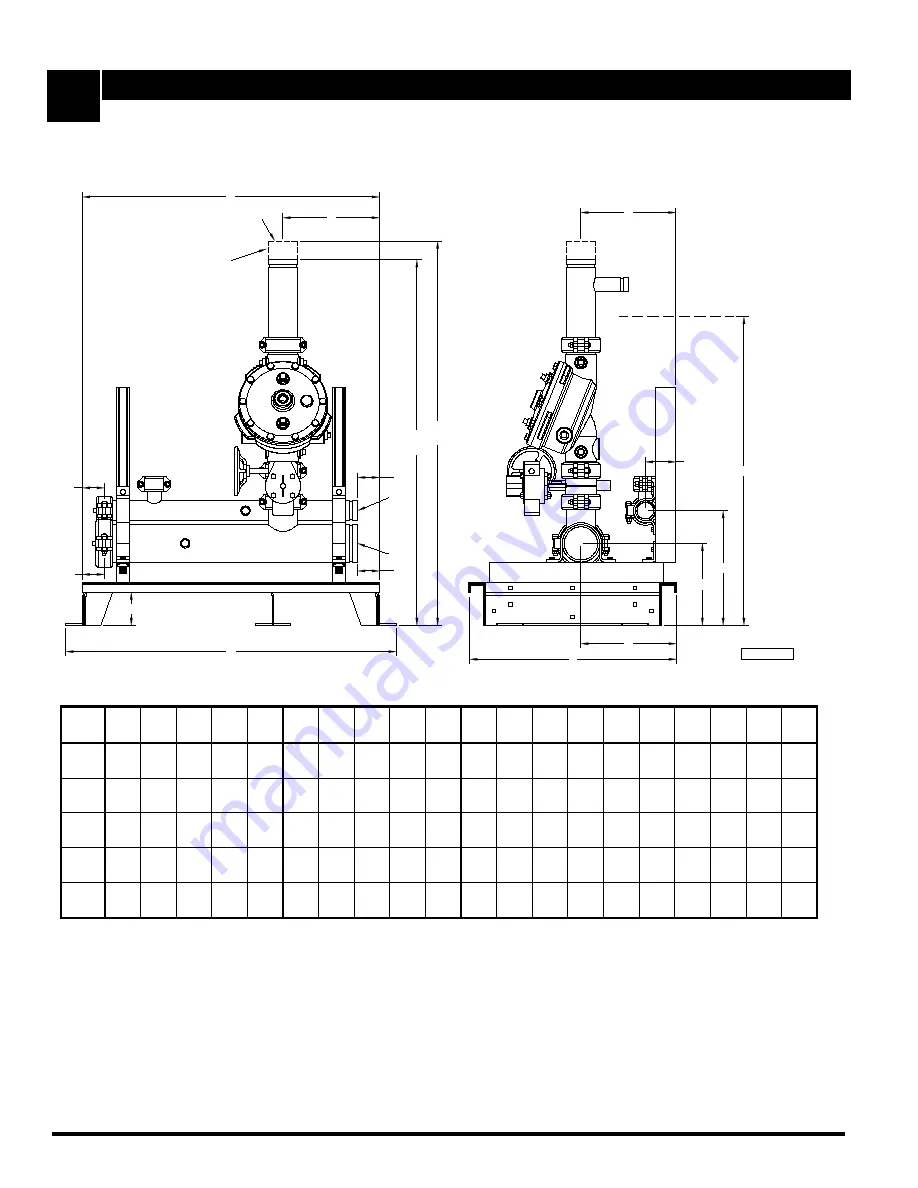
Dimensional Data & Cabinet - Deluge System


FM-076A-0-108A 

Figure 7 - Skid and inlets/outlets dimensions 

(figure is shown without trim for clarity) 

Optional Fire Dep't Connection
Outlet (not shown)

T

Q

A = Main Inlet Manifold Diameter

B = Sprinkler Riser Diameter
C = Drain Manifold Diameter

N

E

F

M

P

G

L

ØA

Optional Shut-off Valve

H

D

L

R

(U)

S

(V)

FM-061H-0-133A

K

ØB

ØC

J

M


Table 7 - Cabinet dimensions

 - dimensions are in inches (mm) 

Unit 
size 

1½" 

(40) 

2" 

(51)


1½" 

(38)


2" 

(51)


23" 

(584)


25" 

(635)


4" 

(102)


8¾" 

(222)


11½" 

(292)


13¾" 

(349)


3¾" 

(95)


2¾" 

(70)


2¾" 

(70)


8" 

(203)


11½" 

(292)


27" 

(686)


43" 

(1092)


47" 

(1194)


34¼" 

(870)


48½" 

(1232)


52½" 

(1334)


2" 

(50) 

2" 

(51)


2" 

(51)


2" 

(51)


23" 

(584)


25" 

(635)


4" 

(102)


8¾" 

(222)


11½" 

(292)


13¾" 

(349)


3¾" 

(95)


2¾" 

(70)


2¾" 

(70)


8" 

(203)


11½" 

(292)


27" 

(659)


45¼" 

(1149)


49¼" 

(1251)


34¾" 

(883)


51¾" 

(1314)


55¾" 

(1232)


3" 

(80) 

4" 

(102)


3" 

(76)


2" 

(51)


35¾" 

(908)


25" 

(635)


4" 

(102)


10" 

(254)


11½" 

(292)


13¾" 

(349)


3¾" 

(95)


2½ 

(64)


2½ 

(64)


11½" 

(292)


11½" 

(292)


39¾ 

(1010)


44" 

(1118)


47¾" 

(1213)


37" 

(940)


51" 

(1295)


54¾" 

(1391)


4" 

(100) 

4" 

(102)


4" 

(102)


2" 

(51)


35¾" 

(908)


25" 

(635)


4" 

(102)


10" 

(254)


11½" 

(292)


13¾" 

(349)


3¾" 

(95)


2½ 

(64)


2½ 

(64)


12" 

(305)


11½" 

(292)


39¾ 

(1010)


48½" 

(1232)


53¼" 

(1353)


42" 

(1499)


56½" 

(1435)


61¼" 

(1556)


6" 

(150) 

6" 

(152)


6" 

(152)


2" 

(51)


46" 

(1168)


25" 

(635)


4" 

(102)


11" 

(279)


11½" 

(292)


13¾" 

(349)


3¾" 

(95)


5¼ 

(133)


5¼ 

(133)


17¾" 

(451)


11½" 

(292)


50" 

(1270)


59½" 

(1511)


65¼" 

(1657)


51½" 

(1308)


70½" 

(1791)


76¼" 

(1937)


Notes: 

  1.  Dimensions are nominal and may vary ±¼" (±5mm). 
  2.  Dimensions T, U & V are for optional fire department connection. 

Summary of Contents for TOTALPAC 3 FIRECYCLE III

Page 1: ...FM 076A 0 12A Advanced Integrated Fire Protection System TOTALPAC 3 Owner s Operation and Maintenance Manual DELUGE SYSTEM FIRECYCLE III RELEASE ...

Page 2: ...anual is prohibited While all reasonable efforts have been taken in the preparation of this manual to assure its accuracy FIREFLEX Systems Inc assumes no liability resulting from any errors or omissions in this manual or from the use of the information contained herein TOTALPAC is a registered trademark of FIREFLEX Systems Inc FIREFLEX Systems Inc reserves the right to make changes to this manual ...

Page 3: ...ructions 1 6 Placing the system back in service after operation 1 7 Inspections tests 1 8 Maintenance 2 System trim 2 1 Normal condition Trim Options Section C 1 Shut off valve sight glass 2 Fire department connection 3 Semi and full flanged option 4 OSHPD seismic option N A Section D Control Section Section E 1 Self contained unit with integrated release control panel 1 1 Product description 1 2 ...

Page 4: ...Page iv TOTALPAC 3 Integrated Fire Protection System OWNER S OPERATION MAINTENANCE MANUAL FM 076A 0 12A Dimensional Data Cabinet Section G 1 Cabinet unit 2 Skid mounted unit Limited Warranty Section H ...

Page 5: ...ovals In addition to being fabricated under tight ISO 9001 manufacturing and quality control procedures your TOTALPAC 3 FIRECYCLE III unit has also been tested and approved by recognized laboratories Here is the list of Listings Approvals it meets Underwriters Laboratories Inc UL Deluge TOTALPAC 3 systems are UL Listed under Special System Water Control Valves Assembled Units category VKYL EX4641 ...

Page 6: ... is the Halar coated version for use in corrosive environments The valve is rated up to a maximum of 250 PSI WWP 1724 kPa and is available in the following diameters 1 40 mm 3 80 mm 6 150 mm 2 50 mm 4 100 mm 8 200 mm TOTALPAC 3 FIRECYCLE III deluge system is supplied with groove groove flow control valve Unit with flange flange flow control valve is also available on request 6 1 Deluge system The ...

Page 7: ...tions according to manuals issued or consult your distributor or FIREFLEX Systems Inc 10 Make sure that building owner or a delegated representative has received instructions regarding the operation of the system WARNING TOTALPAC 3 FIRECYCLE III unit must be installed in an area not subject to freezing temperatures or physical damage 1 2 Preliminary inspection before placing the system in service ...

Page 8: ...ontrol valve A1 through the priming line which includes a normally open priming valve B1 strainer B2 restricted orifice B3 and spring loaded check valve B4 Water pressure is trapped in the priming chamber of the flow control valve A1 by a spring loaded check valve B4 normally closed solenoid valve F1 normally open solenoid valve F2 PORV B9 pressure operated relief valve and manual emergency releas...

Page 9: ...re patrol in the affected areas After a fire verify that the fire is OUT and that placing the system out of service has been authorized by the appropriate local AUTHORITY HAVING JURISDICTION Sprinklers piping that have been subjected to a fire must be returned to service as soon as possible The entire system must be inspected for damage and repaired or replaced as necessary 1 CLOSE main water supp...

Page 10: ...d that all other valves are in their normal operating position see paragraph 2 1 NORMAL CONDITION of the current section 9 Reset the release control panel see section E CONTROLS 10 Check and repair all leaks 11 Notify the local AUTHORITY HAVING JURISDICTION remote station alarm monitors and those in the affected area that the system is back in service 1 7 Inspections and tests NOTICE The owner is ...

Page 11: ...ragraph 1 5 EMERGENCY INSTRUCTIONS to take the system out of service 2 Perform steps of paragraph 1 6 PLACING THE SYSTEM BACK IN SERVICE AFTER OPERATION 1 7 2 Main drain test A main drain test shall be conducted to determine whether there has been a change in the condition of the water supply piping and control valves Test procedure 1 Record the pressure indicated by the water supply gauge B12 2 I...

Page 12: ...e to ensure good condition and normal water supply pressure 2 Control valve shall be externally inspected The valve inspection shall verify the following a The gauges indicate that normal supply water pressure is being maintained b The valve is free of physical damage c All valves are in the appropriate open or closed position see paragraph 2 1 of the current section d There is no leakage from the...

Page 13: ... for disable switch lights up 2 Valves a Main water supply valve D1 is OPEN b All upstream water supply valves are OPEN c Priming valve B1 is OPEN d Flow test valve B6 is CLOSED e Main drain valve D3 is CLOSED f Alarm test valve B5 is CLOSED g Manual emergency release valve B10 is CLOSED handle in vertical position h All gauge valves are OPEN i Shut off valve D4 is OPEN if applicable 3 Gauges a Wa...

Page 14: ... CONNECTION TO OPEN DRAIN on both sides B12 A1 B5 B13 FM 061H 0 109D Trim components A1 Flow control valve B1 Priming valve N O B2 Strainer B3 1 16 1 6 mm Restricted orifice B4 Spring loaded check valve B5 Alarm test valve N C B6 Flow test valve N C B7 Drip check valve N O B8 Drain check valve B9 PORV pressure operated relief valve B10 Manual emergency release valve N C shown in closed position B1...

Page 15: ...y D5 4 Once tests are completed make sure the main drain valve D3 is completely CLOSED Return the system in service as per section B PLACING THE SYSTEM BACK IN SERVICE 5 Fully OPEN the shut off valve D4 Reset the release control panel as per section E CONTROL BUTTONS Figure 1 Shut off valve sight glass figure is shown without cabinet for clarity Supervised shut off valve D4 Point flash light here ...

Page 16: ...ion The full flanged option is the same as above but goes a step further with the main components being also provided with a flanged flanged configuration When provided the face of the flanges will always be located 6 inches from the outside face of the mounting base or cabinet surface On skid unit the surface of the flange on the outlet riser will always be 6 inches above the dimension shown on t...

Page 17: ...ion operation and instruction manual provided with the TOTALPAC 3 unit Pre configured programs allow field programming for one of ten possible input output combinations that are available and listed for use with the TOTALPAC 3 system A field wiring electrical junction boxes is integrated with the cabinet for connection of detection system auxiliary contacts and signaling devices All supply inputs ...

Page 18: ...not be silenced The panel must be reset to silence audible devices SYSTEM RESET The RESET button breaks power to all initiating circuits 4 wire smoke detectors power and will clear any activated output circuits If any alarm supervisory or trouble still exists after reset they will reactivate the control panel 1 6 Time date settings 1 Slide the program switch down to PROGRAM position 2 Press on FUN...

Page 19: ...TALPAC 3 Page 3 of 8 Integrated Fire Protection System E Control Section FM 076A 0 97A Figure 1 Cabinet layout FM 061H 0 126A 3 WATER INLET PRESSURE PRIMING PRESSURE MANUAL EMERGENCY RELEASE CONTROL PANEL ...

Page 20: ...IRCUIT OUTPUT 3 SUPERVISORY BELL OUTPUT 4 BATT NON POWER LIMITED SUPERVISED COM NO NC TROUBLE COM NO NC ALARM COM NO SUPV COM NO WTRFLW RUN SET ZONE 3 ZONE 2 ZONE 1 OUTPUT 2 OUTPUT 1 OUTPUT 3 OUTPUT 4 RESETTABLE POWER SW5 5 DISABLE SWITCH SYSTEM DISABLED SYSTEM NORMAL RELEASING CIRCUIT UNLATCH TO OPEN THE RIGHT DOOR or rotate the control panel 12VDC BATTERY SET AIR COMPRESSOR ISOLATING SWITCH E15 ...

Page 21: ...S485 FM 061H 0 150B NOTE Junction box is located behind the control panel once rotated It is shown with cover removed All conduits are installed by the Contractor through 1 2 and 3 4 knock outs TBB TBA TBC Refer to Electrical Section for Wiring Diagrams TBA TBC Terminals TBB Terminals AC POWER 120VAC 50 60Hz or 220 240VAC 50 60Hz OPTIONAL ARM 44 RELAY MODULE POWER LIMITED CIRCUITS F ...

Page 22: ...ions box is integrated with the cabinet for connection of pressure switches supervisory switches etc in the trim is factory wired to a terminal strip TBA TBC for contractor s field wiring see figure 4 and the section F ELECTRICAL 2 2 Technical data Steel enclosure Refer to section G CABINET SECTION for further details Environment electrical section 39 F 4 C minimum Figure 5 Cabinet layout PRIMING ...

Page 23: ...trol panel F POWER LIMITED CIRCUITS FM 061H 0 279A All conduits are installed by the Contractor through 1 2 and 3 4 knock outs SYSTEM DEVICES OPT TBA Releasing circuit Disconnect switch TBA Optional TBC Terminals POWER LIMITED CIRCUITS DISABLE SWITCH SYSTEM DISABLED SYSTEM NORMAL RELEASING CIRCUIT TBC Refer to Electrical Section for Wiring Diagrams ...

Page 24: ...Page 8 of 8 TOTALPAC 3 E Integrated Fire Protection System Control Section FM 076A 0 97A This page is left intentionally blank ...

Page 25: ...dible devices sound and if required can be silenced manually The N C normally closed solenoid valve of the system is energized allowing the water to escape from the priming chamber of the deluge valve The clapper of the deluge valve opens filling the outlet chamber and sprinklers piping network with water The DETECTION ZONE 3 water flow is activated System water flow audible devices and the water ...

Page 26: ...shown in their normal supervisory state NOTES Use dry contacts with power limited circuits only CONTACTS RATED 5A 1 6HP 125 250VAC 0 5A 250VDC 0 25A 250VDC N C HEAT DETECTOR MANUAL RELEASE DRY CONTACT END OF LINE RESISTOR LEGEND BELL OR HORN Control panel AC power source is supervised and non power limited 5 1KV EOLR 5 1KV EOLR 5 1KV EOLR 5 1KV EOLR WIRING IN CLASS B STYLE Y WIRING IN CLASS B STYL...

Page 27: ... NC 3 Selector switch must be set according to the total number of devices installed on the RS 485 terminals Increment for each device being added 7 OUTPUT 4 COM 24 MODE 2 NO Card address switch must be set one value higher than the previous one Set the selector switch at the VFR 400 accordingly Relocate existing wires from TBC 1 to 4 to TB1 1 to 4 of ARM 44 then rewire 4 new cables from TB1 1 to ...

Page 28: ... 120V 8 4 Annunciator Side 2 RED OUTPUT LED STEADY ABORT S 4 TBC Connections Side FM 061H 0 81A 2 4 1 7 OUTPUT 4 3 Selector switch must be set according to the total number of devices installed on the RS 485 terminals Increment for each device being added Annunciator address switch must be set one value higher than the previous one Set the selector switch at the VFR 400 accordingly OUTPUT 2 Connec...

Page 29: ...gs N O SOLENOID VALVE 1 TBC 2 3 4 5 6 C NO NC MAIN VALVE SUPERVISORY C NO NC SHUT OFF VALVE SUPERVISORY Contacts provided for connection to the building s central Fire Alarm Panel OPTIONAL LOS ANGELES OPTION CHICAGO OPTION NOTE MAIN VALVE SUPERVISORY SWITCH SHUT OFF VALVE SUPERVISORY SWITCH 1 TBA 2 3 4 5 6 7 8 9 10 11 12 13 14 15 16 21 22 23 24 WATER FLOW ALARM WATER FLOW PRESURE SWITCH EOL MAIN V...

Page 30: ...ch A key switch located at the front of the junctions box allows the user to electrically disconnect the N C solenoid valve for maintenance purpose A supervisory contact is to be wired to the release control panel When disabled the TOTALPAC 3 FIRECYCLE III unit remains operational with the opening of the manual emergency release valve unless the main water supply valve is closed ...

Page 31: ...IN DETAILS FOR MULTIPLE UNITS IMPORTANT TotalPac 3 unit is NOT designed to be installed where it will be subjected to outdoors and or freezing conditions Refer to paragraph 3 ENVIRONMENT in section A GENERAL DESCRIPTION for additional details Subjecting the unit to conditions outside these limitations might hamper the normal operation of the system The release control panel of the TotalPac 3 syste...

Page 32: ...3 95 2 70 2 70 8 203 11 292 27 686 43 1092 47 1194 34 870 48 1232 52 1334 2 50 2 51 2 51 2 51 23 584 25 635 77 1956 4 102 8 222 11 292 13 349 3 95 2 70 2 70 8 203 11 292 27 686 45 1149 49 1251 34 883 51 1314 55 1232 3 80 4 102 3 76 2 51 35 908 25 635 77 1956 4 102 10 254 11 292 13 349 3 95 2 70 2 70 11 298 11 292 39 1010 44 1118 47 1213 37 940 51 1295 54 1391 4 100 4 102 4 102 2 51 35 908 25 635 7...

Page 33: ...m 56 1422mm 21 530mm Figure 3 Cabinet doors clearance detail TOTALPAC 3 UNIT FM 061H 0 275A 1 B min C min A min B min TYPICAL MECHANICAL ROOM Figure 4 Knockouts details 2 Typ 65mm 9 230mm High voltage Low voltage Combined knockouts 2 65mm FM 061H 0 68B 12 Top of Cabinet 8 215mm 3 75mm Table 4 Cabinet clearance dimensions Unit size A B C 1 40mm 24 610mm 12 305mm 48 1219mm 2 50mm 24 610mm 12 305mm 4...

Page 34: ...0mm 13 350mm 2 50mm 8 200mm 12 305mm 17 445mm 2 50mm Figure 6 Open drain details for multiple units refer to dimensions in table 5 TOTALPAC 3 Unit Shown Without Front Doors Drain Collector running between wall and units pipe diameter per drain flow calculations Typical Air Gap TOTALPAC 3 Unit Shown Without Front Doors 4 100mm min B FM 061H 0 140A A 12 305mm min Multiple Units Detail Water Supply P...

Page 35: ...r powder on phosphate base Multiple units installation is easily achieved by jointing manifold sections together at their water inlets Drains outlet shall remain separate and open for each unit Refer to figure 11 OPEN DRAIN DETAILS FOR MULTIPLE UNITS IMPORTANT TotalPac 3 unit is NOT designed to be installed where it will be subjected to outdoors and or freezing conditions Refer to paragraph 3 ENVI...

Page 36: ... 8 222 11 292 13 349 3 95 2 70 2 70 8 203 11 292 27 686 43 1092 47 1194 34 870 48 1232 52 1334 2 50 2 51 2 51 2 51 23 584 25 635 4 102 8 222 11 292 13 349 3 95 2 70 2 70 8 203 11 292 27 659 45 1149 49 1251 34 883 51 1314 55 1232 3 80 4 102 3 76 2 51 35 908 25 635 4 102 10 254 11 292 13 349 3 95 2 64 2 64 11 292 11 292 39 1010 44 1118 47 1213 37 940 51 1295 54 1391 4 100 4 102 4 102 2 51 35 908 25 ...

Page 37: ...size A B 1 40mm 25 635mm 15 380mm 2 50mm 25 635mm 15 380mm 3 80mm 37 959mm 15 380mm 4 100mm 37 959mm 15 380mm 6 150mm 48 1220mm 15 380mm Figure 9 Skid clearance detail B min A min TYPICAL MECHANICAL ROOM TOTALPAC 3 SKID UNIT FM 061H 0 275A 2 B min Table 9 Skid clearance dimensions Unit size A B 1 40mm 48 1219mm 12 305mm 2 50mm 48 1219mm 12 305mm 3 80mm 60 1524mm 12 305mm 4 100mm 60 1524mm 12 305mm...

Page 38: ...0mm 10 255mm 13 350mm 2 50mm 6 150mm 11 280mm 13 350mm 2 50mm Figure 11 Open drain details for multiple units refer to dimensions in table 10 B Typical Air Gap A Water Supply Pipe Can Be Manifolded Drain Collector running between wall and units pipe diameter per drain flow calculations Unit Drain Pipe dia C DO NOT MANIFOLD FM 061H 0 138A 4 100mm min Multiple Units Detail 12 min Notes 1 Water suppl...

Page 39: ...fits inconveniences transportation charges or other damages suffered by anyone There are no other warranties expressed or implied with regard to the products other than those contained herein Some jurisdictions may not allow limitations on how long an expressed warranty lasts so the above limitations may not apply to you Under no circumstances shall the Manufacturer be liable for any loss of or da...

Page 40: ...Page 2 of 2 TOTALPAC 3 H Integrated Fire Protection System Limited Warranty FM 076A 0 96C User Notes ...

Reviews:

Related manuals for TOTALPAC 3 FIRECYCLE III