
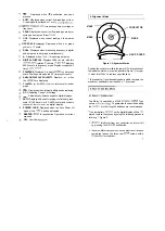
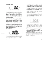

5.9 Measuring Resistance
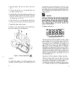
5.10 Continuity Testing
Press the pushbutton enable the resistance
ment mode. This Meter defaults in the autoranging mode and
displays KR and AUTO. And also the
arrow of the
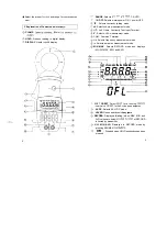
bar graph blinks and the digital display reads OFL.
AUTO (autoranging) applied to the bar graph.
This Meter measures resistance by comparing the internal
reference resistance given by a resistor array with the
unknown resistance
be measured. Remember, the
sistance displayed by this Meter
the total resistance
through all possible paths between the probes. This explains
why in-circuit measurement of resistors does not
yield
the ohms value indicated by the resistor’s
CAUTION!
TURN OFF POWER ON THE TEST
AND
CHARGE ALL CAPACITORS BEFORE ATTEMPTING
CIRCUIT RESISTANCE MEASUREMENTS.
AN
TERNAL VOLTAGE
PRESENT ACROSS A
PONENT, IT WILL BE IMPOSSIBLE TO TAKE AN
CURATE MEASUREMENT OF THE RESISTANCE OF
THAT COMPONENT.
The resistance in the
leads
diminish accuracy on
i
the lowest
range. The error
0.1 to 0.2
ohms for a Standard pair of test
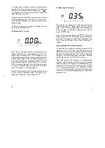
Press the
l
$j
pushbutton enable the continuity testing
mode. This Meter
in the
range and then
highest bar graph
400. The digital display reads
OFL.
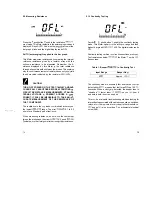
Continuity testing verifies
circuit connections are
Test resistances below
the Meter emit a
tinuous tone.
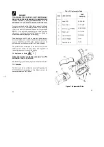
Table 1. Beeper
in Continuity Test
Input Range
Beeper On
Approx.
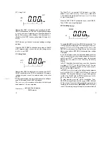
The continuity mode is extremely fast and
be
detect either
or opens that last for as
as 100
liseconds. When a
detected, the beeper tone is
“stretched” last at least
so you
hear it
and detect both
and opens.
This
be a valuable troubleshooting aid when looking for
intermittents associated with cables connections, switches,
relays, etc. the
value is very
to the threshold,
beeps
also occur due environmental electrical
noise (EMI).
When measuring resistance, be sure
the contact
tween the probes and the circuit
good.
Oil,
or other foreign matter seriously
resistance.
14
15
Summary of Contents for FINEST 135
Page 16: ......


