background image

SPEED LEVEL MENU (TRACTION SPEED SETS)

Proceed as follows to change the "SPEED LEVEL” parameter in the Speed sets menu:

1. 

Display the "MACHINE BRUSHES SETTINGS" menu - see 

“SETTINGS MENU” on page 9

.

2. 

Display the “SERVICE” menu - see 

“SERVICE MENU” on page 16

.

3. 

Display the “PARAMETERS” menu - see 

“PARAMETERS MENU (SERVICE)” on page 17

.

4. 

Display the “TRACTION” menu , see 

“TRACTION SETS MENU (PARAMETERS)” on page 56

.

5. 

Display the “SPEED SETS” menu , see 

“SPEED SETS MENU (TRACTION SETS)” on page 59

.

6. 

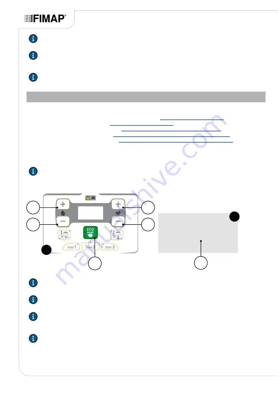
Using buttons (1) and (2) (

Fig.1

) select the "SPEED LEVEL" screen (

Fig.2

).

7. 

As soon as the "SPEED LEVEL" screen (

Fig.2

) is displayed, select the forward speed of the machine in the 

working phase using the buttons (3) and (4) (

Fig.1

).

N.B.:

 the selected value will be visible in the text string (5) in the lower part of the screen (

Fig.2

).

8. 

Confirm the selection by pressing the button (6) (

Fig.1

).

Vacuum

Vac. motor

60

[%]

Vacuum noise level 1:

min:10

max:100

2

5

2

4

1

3

6

1

N.B.:

 the “SPEED LEVEL” parameters represent the forward speed of the machine when working.

N.B.:

 the “SPEED LEVEL” parameters correspond to the performance levels of the forward speed.

N.B.:

 The “SPEED LEVEL” parameters are expressed as a percentage (%) with respect to the MODE2 

SPEED (WORK SPEED), the numerical value is between a minimum of 010 and a maximum of 100, the 

selectable increment is two units.

N.B.:

 the “SPEED LEVEL” parameters are set to the following numbers in the factory:

• 

SPEED LEVEL #1= 50

• 

SPEED LEVEL #2= 75

• 

SPEED LEVEL #3= 100

N.B.:

 The “MODE2 SPEED (WORK SPEED)” parameter is the maximum speed the machine can reach 

when working.

N.B.:

 The “MODE2 SPEED (WORK SPEED)” parameter is expressed as a percentage (%) with respect to 

the MAX SPEED FORWARD, the numerical value is between a minimum of 10 and a maximum of 100, the 

selectable increment is one unit.

N.B.:

 The “MODE2 SPEED (WORK SPEED)” parameter is set in the factory to 90.

Page 60

Summary of Contents for GMG PRO

Page 1: ...al including the structure text diagrams images and logo are the exclusive property of FIMAP S P A They are protected both collectively and individually by the current regulations regarding intellectu...

Page 2: ......

Page 3: ...GENERAL SETS 22 BATTERY TYPE MENU GENERAL BATTERY 22 CUSTOM LEVEL MENU GENERAL BATTERY 23 HOUR METER MENU GENERAL SETS 24 VISUALIZED HMT MENU GENERAL HOURMETER 24 HMT PARTIAL RESET MENU GENERAL HOURME...

Page 4: ...8 VACUUM NOISE LEVEL MENU VACUUM SWEEP MOT 49 OPTIONAL SETS MENU PARAMETERS 50 OPT BRUSH MENU OPTIONAL SETS 50 RESET DELAY MENU OPTIONAL OPT BRUSH 51 OPT SWEEP MENU OPTIONAL SETS 52 RESET DELAY MENU O...

Page 5: ...AY CONTRAST on page 15 CHANGING THE MACHINE POWER SUPPLY BATTERY TYPE on page 11 CHANGING THE PERCENTAGE OF CHEMICAL PRODUCT IN THE DETERGENT SOLUTION on page 13 LANGUAGE SELECTION MENU on page 10 DIS...

Page 6: ...L ACCESSMODE on page 28 PASSWORD PROTECTION PIN MENU GENERAL ACCESSMODE on page 29 ANTI COLLISION MENU GENERAL CONFIG on page 30 SIDE BRUSH MENU GENERAL CONFIG on page 30 HAZARD LIGHTS MENU GENERAL CO...

Page 7: ...AMETERS on page 46 OPTIONAL SETS MENU PARAMETERS on page 50 ACTUATOR SETS MENU PARAMETERS on page 54 TRACTION SETS MENU PARAMETERS on page 56 RESET DELAY MENU OPTIONAL OPT BRUSH on page 51 RESET DELAY...

Page 8: ...ENU To navigate through the menus use the buttons 1 Button for scrolling to the next parameter 2 Button for scrolling to the next parameter 3 Confirm button 4 Button to increase the value selected by...

Page 9: ...ry Type Allows to select the type of battery that powers the machine see CHANGING THE MACHINE POWER SUPPLY BATTERY TYPE on page 11 Percentage Chemical Allows to change the amount of detergent present...

Page 10: ...LANGUAGE on page 10 CHANGING THE DISPLAY LANGUAGE Proceed as follows to change the display language 1 Display the GENERAL MACHINE SETTINGS menu see SETTINGS MENU on page 9 2 Display the LANGUAGE SELE...

Page 11: ...SUPPLY BATTERY TYPE To change the type of power supply battery of the machine carry out the following 1 Display the GENERAL MACHINE SETTINGS menu see SETTINGS MENU on page 9 2 Display the BATTERY TYPE...

Page 12: ...ee SETTINGS MENU on page 9 2 From the GENERAL MACHINE SETTINGS menu using the buttons 1 and 2 Fig 1 select the screen dedicated to the CHEMICAL PERCENTAGE menu Fig 2 2 1 1 Pump Water 2 0 Chemical perc...

Page 13: ...lower part of the screen Fig 2 4 Confirm the selected percentage by pressing the button 4 Fig 1 2 1 4 1 General Main 2 0 Chemical percentage min 0 5 max 3 0 2 3 N B the increase in the percentage take...

Page 14: ...t level takes place in steps of 1 unit at a time the minimum allowed value is 0 while the maximum allowed value is 50 4 Confirm the contrast level of the display by pressing the button 4 Fig 1 2 1 4 1...

Page 15: ...GHTNESS screen Fig 2 appears adjust the display brightness using buttons 1 and 2 Fig 1 N B the brightness level of the display will be visible in the text string 3 in the lower part of the screen Fig...

Page 16: ...o access the service menu N B if the entered password is correct and the security level is correct access is granted to the SERVICE MENU screen The following sub menus can be selected on the Service m...

Page 17: ...d or change the parameters of the machine s scrubbing system see BRUSHES SETS MENU PARAMETERS on page 34 Pump Sets This is used to display and or change the parameters of the machine s water unit see...

Page 18: ...select the type of battery that powers the machine see BATTERY TYPE MENU GENERAL BATTERY on page 22 Used to modify the discharge curve of the CUSTOM battery type see CUSTOM LEVEL MENU GENERAL BATTERY...

Page 19: ...he GENERAL SETS menu see GENERAL SETS MENU PARAMETERS on page 18 5 Using buttons 1 and 2 Fig 1 select the GENERAL main screen Fig 2 and press button 3 to confirm the display Fig 1 2 1 1 Main 2 General...

Page 20: ...S menu see PARAMETERS MENU SERVICE on page 17 4 Display the GENERAL SETS menu see GENERAL SETS MENU PARAMETERS on page 18 5 Display the MAIN menu see MAIN MENU GENERAL SETS on page 19 6 Using buttons...

Page 21: ...and 2 Fig 1 select the DISPLAY TUNE screen Fig 2 7 As soon as the DISPLAY BRIGHTNESS screen Fig 2 is displayed adjust the display brightness using buttons 3 and 4 Fig 1 N B the brightness level of th...

Page 22: ...out the following 1 Display the GENERAL MACHINE SETTINGS menu see SETTINGS MENU on page 9 2 Display the SERVICE menu see SERVICE MENU on page 16 3 Display the PARAMETERS menu see PARAMETERS MENU SERV...

Page 23: ...TERY menu see BATTERY MENU GENERAL SETS on page 22 6 Using buttons 1 and 2 Fig 1 select the LANGUAGE SELECTION screen Fig 2 7 As soon as the LANGUAGE SELECTION screen Fig 2 is displayed select the lan...

Page 24: ...he following 1 Display the GENERAL MACHINE SETTINGS menu see SETTINGS MENU on page 9 2 Display the SERVICE menu see SERVICE MENU on page 16 3 Display the PARAMETERS menu see PARAMETERS MENU SERVICE on...

Page 25: ...8 Confirm the hour meter reset operation by pressing the button 6 Fig 1 2 4 1 3 6 1 General Hour meter Partial reset hmt No 2 5 The following can be selected in the partial hour meter type selection...

Page 26: ...e SETTINGS MENU on page 9 2 Display the SERVICE menu see SERVICE MENU on page 16 3 Display the PARAMETERS menu see PARAMETERS MENU SERVICE on page 17 4 Display the GENERAL SETS menu see GENERAL SETS M...

Page 27: ...User min 1000 max 1999 2 5 2 4 1 3 6 1 N B the password set in the factory is 1000 the new password must be between 1000 and 1999 PASSWORD 5 PIN MENU GENERAL ACCESSMODE To change the level 5 PIN pass...

Page 28: ...NERAL SETS on page 26 6 Using buttons 1 and 2 Fig 1 select the PASSWORD PROTECTION USER screen Fig 2 7 As soon as the PASSWORD PROTECTION USER screen Fig 2 is displayed use buttons 3 and 4 Fig 1 to se...

Page 29: ...ed value will be visible in the text string 5 in the lower part of the screen Fig 2 8 Confirm the selection by pressing the button 6 Fig 1 General AccessMode 0 Password protection PIN min 0 max 1 2 5...

Page 30: ...4 Fig 1 N B the selected parameter will be visible in the text string 5 in the lower part of the screen Fig 2 8 Confirm the selected hour meter by pressing the button 6 Fig 1 2 4 1 3 6 1 General Confi...

Page 31: ...the selected parameter will be visible in the text string 5 in the lower part of the screen Fig 2 8 Confirm the selected hour meter by pressing the button 6 Fig 1 7 As soon as the ANTI COLLISION scree...

Page 32: ...play the PARAMETERS menu see PARAMETERS MENU SERVICE on page 17 4 Display the GENERAL SETS menu see GENERAL SETS MENU PARAMETERS on page 18 5 Display the CONFIG menu see CONFIG MENU GENERAL SETS on pa...

Page 33: ...SETS on page 29 6 Using buttons 1 and 2 Fig 1 select the ZONE OPERATION ENABLE screen Fig 2 7 As soon as the ZONE OPERATION ENABLE appears Fig 2 use the buttons 3 and 4 Fig 1 to select the management...

Page 34: ...H MOT on page 36 Used to modify the parameter relating to the pressure levels exerted on the scrubbing brush head see PRESSURE LEVEL MENU BRUSHES BRUSH MOT on page 37 Used to modify the parameter rela...

Page 35: ...the MACHINE BRUSHES SETTINGS menu see SETTINGS MENU on page 9 2 Display the SERVICE menu see SERVICE MENU on page 16 3 Display the PARAMETERS menu see PARAMETERS MENU SERVICE on page 17 4 Display the...

Page 36: ...n the text string 5 in the lower part of the screen Fig 2 8 Confirm the selection by pressing the button 6 Fig 1 Brushes Brush Mot 100 Speed REDUCTION min 10 max 100 2 5 2 4 1 3 6 1 N B the SPEED REDU...

Page 37: ...work phase using buttons 3 and 4 Fig 1 N B the selected value will be visible in the text string 5 in the lower part of the screen Fig 2 8 Confirm the selection by pressing the button 6 Fig 1 Brushes...

Page 38: ...n Fig 2 8 Confirm the selection by pressing the button 6 Fig 1 Brushes Brush Mot 4 0 A Pressure range min 0 max 4 0 2 5 2 4 1 3 6 1 N B the PRESSURE RANGE parameter represents the value of the maximum...

Page 39: ...2 is displayed select the delay in seconds before the actuator brings the brush head to the raised from the floor position using buttons 3 and 4 Fig 1 N B the selected value will be visible in the tex...

Page 40: ...1 3 6 1 N B the SPEED REDUCTION parameter represents the recovery voltage from the ammeter protection tripping condition N B The SPEED REDUCTION parameter is expressed as a percentage with respect to...

Page 41: ...ent absorbed by the pressure levels before the tripping of the ammeter resistance protection using buttons 3 and 4 Fig 1 N B the selected value will be visible in the text string 5 in the lower part o...

Page 42: ...the current absorbed by the pressure level before the tripping of the ammeter resistance protection while working N B The PRESSURE RANGE parameter is expressed in amperes A the numerical value is bet...

Page 43: ...UMP on page 44 PUMP CHEMICAL Used to modify the parameter relating to the percentage of chemical product dispensed valid only for programs that do not allow the parameters to be changed manually see C...

Page 44: ...p Water 40 Pump level 1 min 0 max 150 2 5 2 4 1 3 6 1 N B the PUMP LEVEL Sum parameters represent the quantity of detergent solution that is delivered by the machine while working N B the PUMP LEVEL S...

Page 45: ...text string 5 in the lower part of the screen Fig 2 8 Confirm the selection by pressing the button 6 Fig 1 Pump Chemical 2 0 Chemical Percentage min 0 5 max 3 0 2 5 2 4 1 3 6 1 N B the CHEMICAL PERCEN...

Page 46: ...the floor position see RESET DELAY MENU VACUUM VAC MOT on page 47 Used to modify the parameters relating to the performance levels of the machine s vacuum system see VACUUM NOISE LEVEL MENU VACUUM VA...

Page 47: ...s in the working position before lifting off the ground N B The RESET DELAY parameter is expressed in seconds s the numerical value is between a minimum of 001 and a maximum of 300 the selectable incr...

Page 48: ...reen Fig 2 8 Confirm the selection by pressing the button 6 Fig 1 Vacuum Vac motor 60 Vacuum noise level 1 min 10 max 100 2 5 2 4 1 3 6 1 N B the VACUUM NOISE LEVEL parameters represent the suction mo...

Page 49: ...the machine using buttons 3 and 4 Fig 1 N B the selected value will be visible in the text string 5 in the lower part of the screen Fig 2 8 Confirm the selection by pressing the button 6 Fig 1 Vacuum...

Page 50: ...re the actuator moves the side brush to the lifted off the floor position see RESET DELAY MENU OPTIONAL OPT BRUSH on page 51 OPT SWEEP Used to modify the parameter relating to the standby time before...

Page 51: ...creen Fig 2 is displayed select the delay in seconds before the actuator brings the side brush to the raised from the floor position using buttons 3 and 4 Fig 1 N B the selected value will be visible...

Page 52: ...y the MACHINE BRUSHES SETTINGS menu see SETTINGS MENU on page 9 2 Display the SERVICE menu see SERVICE MENU on page 16 3 Display the PARAMETERS menu see PARAMETERS MENU SERVICE on page 17 4 Display th...

Page 53: ...remain in the working position before lifting off the floor N B The RESET DELAY parameter is expressed in seconds s the numerical value is between a minimum of 001 and a maximum of 300 the selectable...

Page 54: ...vacuum menu screen SQUEEGE Used to modify the parameter relating to the standby time before the actuator moves the squeegee to the lifted off the floor position while reversing see TRACTION REVERSE DE...

Page 55: ...splayed select the delay in seconds before the actuator brings the squeegee to the raised from the floor position when reverse is engaged using buttons 3 and 4 Fig 1 N B the selected value will be vis...

Page 56: ...in English The following sub menus can be selected on the vacuum menu screen PAR CHANGE Used to modify the parameter relating to the maximum forward speed in TRANSFER mode see MAX FORWARD SPEED MENU T...

Page 57: ...nge menu 1 Display the MACHINE BRUSHES SETTINGS menu see SETTINGS MENU on page 9 2 Display the SERVICE menu see SERVICE MENU on page 16 3 Display the PARAMETERS menu see PARAMETERS MENU SERVICE on pag...

Page 58: ...menu see TRACTION SETS MENU PARAMETERS on page 56 5 Display the PAR CHANGE menu see PAR CHANGE MENU TRACTION SETS on page 57 6 Using buttons 1 and 2 Fig 1 select the MAX SPEED FORWARD screen Fig 2 7...

Page 59: ...change menu 1 Display the MACHINE BRUSHES SETTINGS menu see SETTINGS MENU on page 9 2 Display the SERVICE menu see SERVICE MENU on page 16 3 Display the PARAMETERS menu see PARAMETERS MENU SERVICE on...

Page 60: ...ssing the button 6 Fig 1 Vacuum Vac motor 60 Vacuum noise level 1 min 10 max 100 2 5 2 4 1 3 6 1 N B the SPEED LEVEL parameters represent the forward speed of the machine when working N B the SPEED LE...

Page 61: ...system Brushes The icon identifies the hour meter relative to the electrical motors in the brush head scrubbing system Vacuuming The icon identifies the hour meter relative to the electrical motors i...

Page 62: ...g 3 N B the text string 5 identifies the alarm number displayed Fig 3 N B the text string 6 identifies the group to which the displayed alarm belongs Fig 3 N B the text string 7 identifies the descrip...

Page 63: ...ction Ammeter it is not used for this type of machine Brush 1 Current this indicates the instantaneous current absorbed by gearmotor 1 located in the central brush head of the machine the value is exp...

Page 64: ...4 N B after the selection to be displayed it will be visible in the main screen instead of the hour meter 4 Page 64...

Page 65: ...Page 65...

Page 66: ...Page 66...

Page 67: ......

Page 68: ...FIMAP S p A Via Invalidi del Lavoro 1 37059 S Maria di Zevio VR Italy 39 045 6060491 39 045 6060440 service fimap com www fimap com...

Reviews: