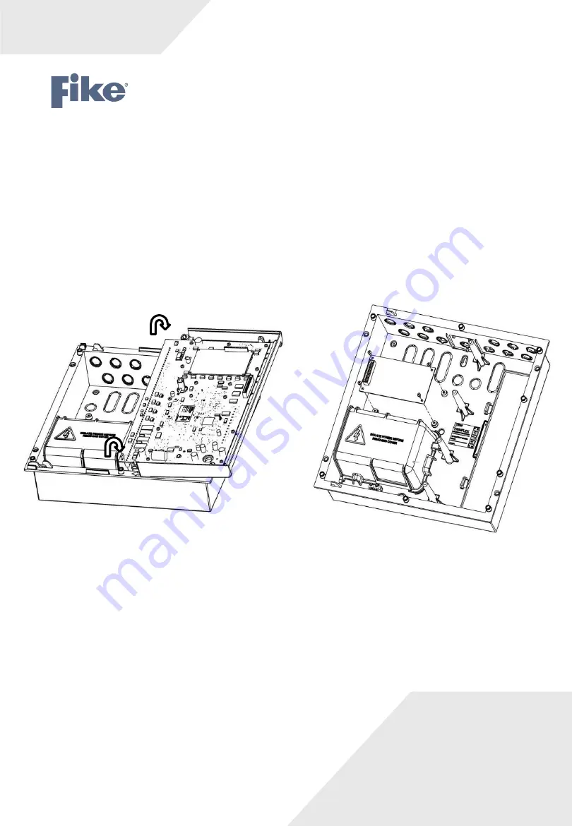
6. Secure the expansion card PCB to the
unit’s base using the 4 off M3 x 6 screws supplied
(Fig 3). Please note the orientation of the expansion card PCB.
7.
Plug one end of the ribbon cable assembly into the expansion card PCB (this will only fit one way).
8.
Flip the left hand CIE assembly back over clockwise (reverse fig 2) and plug the other end of the ribbon
cable assembly into the connector marked (expansion connector) on the CIE PCB (again this will only
fit one way).
9.
Secure the CIE assembly onto the base molding (Fig 1) (ensure that all cables ends are accessible for
termination) and secure into position.
10. Re-connect all existing cables to the appropriate terminals.
11. If the new additional zones are to be used straight away, connect the additional field wiring zone cables to
the relevant terminals on the TwinflexPro² panel CIE (they do not connect directly to the Expansion Card).
12. Re-connect the mains power to the panel (before connecting the battery) by refitting the fuse in the fused
spur that supplies the panel or switching on the circuit breaker.
13. Now re-connect the battery.
14. Refit the right hand cover (ensure the cover engages
properly into the CIE assembly moulding) and secure into position.
Fig 3
Fig 2
26-1509 Issue 2


