


SBPC-21-EN/IP CUSTOMER INSTRUCTION MANUAL
________________________________________________________________________________________________________________
12-20-2002
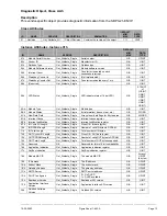
Figure Sheet 1-853-A
Page 15
2
F
IFE
N
ET
T
HEORY
• • • • • •
FifeNet Time Slices
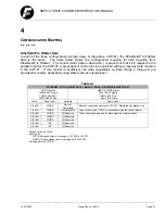
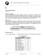
Data on FifeNet is divided into time intervals called time slices. The FifeNet protocol runs in fixed
repeating cycles. Each time slice can transmit a single 16-bit value. All time slice values are updated
every cycle.
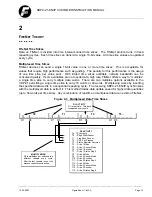
Multiplexed Time Slices
FifeNet devices can send a single 16-bit value in one or more time slices. This is acceptable for
values that require high performance such as guiding. The penalty for this performance is the usage
of one time slice per value sent. With limited time slices available, network bandwidth can be
consumed quickly. If some variables are not needed at a high rate, FifeNet offers a way to “multiplex”
a single time slice to carry multiple data words. There are two multiplex options available in the
CDP-01 permitting a single time slice to carry 16 words or 64 words. Multiplexing works by inserting
the specified data words in a sequential repeating cycle. The receiving SBPC-21-EN/IP synchronizes
with the multiplexed data to extract it. This method trades data update speed for higher data quantities
(up to 64 words per time slice). Any combination of real-time or multiplexed data can exist on FifeNet.
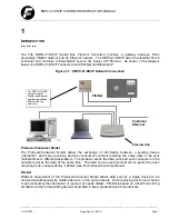
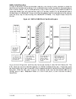
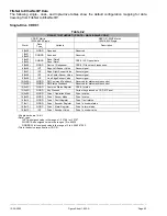
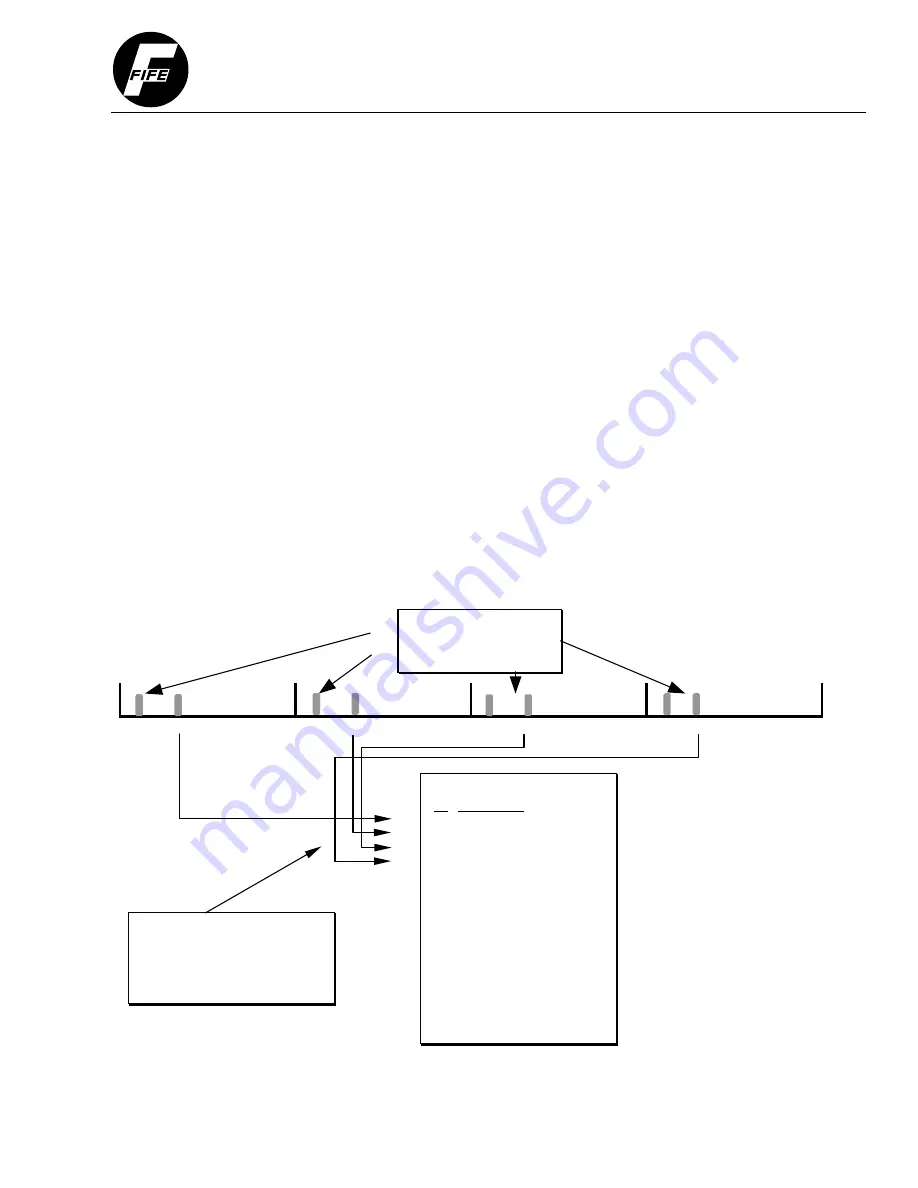
Figure 2-1: Multiplexed Data Time Slices
T0 T1 T2 T3…
−
−−−−−−−−−−−−−−−−−
−
−−−−−−−−−−−−−−−−−
−
−−−−−−−−−−−−−−−−−
−
−−−−−−−−−−−−−−−−−
D1 D5 D1 D5 D1 D5 D1 D5
D1 ACTIVITY
D1 is real-time. This data
is updated every cycle.
D5 ACTIVITY
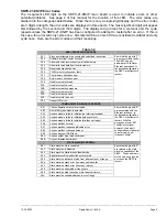
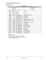
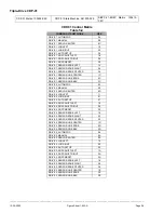
Tn TS Contents
T0 - Edge Right Sensor
T1 - Line Edge Sensor
T2 - CDP Key Pressed
T3 - Status Register Common
T4 - Drive 1 Mode
T5 - Drive 1 Sensor Mode
T6 - Drive 1 Encoder
T7 - Drive 1 Status Reg 0
T8 - Drive 2 Mode
T9 - Drive 2 Sensor Mode
T10 - Drive 2 Encoder
T11 - Drive 2 Status Reg 0
T12 - Drive 3 Mode
T13 - Drive 3 Sensor Mode
T14 - Drive 3 Encoder
T15 - Drive 3 Status Reg 0
MULTIPLEXING
D5 is multiplexed or switched to a
different variable every cycle.
After the last variable is sent, the
process repeats continuously.


