background image

11 

Installation Instructions 

Equipment Setup  

1.  Read User Guide noting all instructions.  Review the dimensions for the unit you are installing.   
 

Verify that it will fit in the space intended for it. 


Verify that the counter or table will support the total weight of the equipment and any dispensers when filled. 

2.  Place the equipment on the counter or stand. 


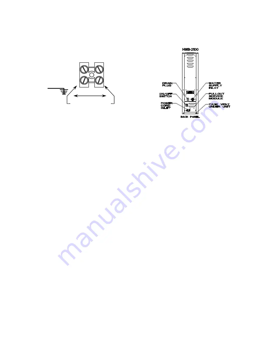
Illustrations above show examples of domesic terminal block and location of connections and utilities. 

Æ

Always refer to the wiring diagrams when connecting equipment electrical utilities 

 
Water Connection 

1.  Water supply inlet is a 

 inch male flare fitting. 

2.  The Hwb-2100 Hot Water Dispenser can be connected to a cold or hot water line.   
 

(Cold water is preferred for best beverage flavor, but hot water will allow for greater output.) 

3.  Install a shut off water valve near the equipment to facilitate service.  An in-line water filter should used and 

installed after the water shut off valve and in a position to facilitate filter replacement. 

4.  Flush the water supply line and filter 

before

 connecting it to the unit. 

5.  Verify that the water line will deliver a flow rate of at least 1½gpm/(5.7lpm) per minute and water pressure is 

between 20-75 psig (138-517kPa) before making any connections. 

6.  Use a wrench on the factory fitting when connecting the incoming water line. This will reduce stress on the 

internal connections and reduce the possibility of leaks developing after the install has been completed. 


Electrical Connection 

1.  The  HWB-2100 model series requires hardwired grounded service to the terminal block (illus. 1) 
2.  Verify that the actual voltage at the electrical service connection is compatible with the specifications on the 

equipment serial number label.  Make sure the electrical service match the current draw of the equipment. 

3.  Access the terminal block for electrical connection by removing the pullout service module on the lower back. 
4.  A fused disconnect switch or circuit breaker on the incoming power line must be conveniently located near the 

equipment and its location and markings known to the operators. 

5.  The body of the unit must be grounded to a suitable building ground. 


6.  If Cord Connected: Do not use multiple taps for the plug.  Consult local codes to determine if a single circuit is 

required for the cord and plug installed.  Do not use extension cords for commercial food equipment 
 

 Tank Drain 

The water tank must be drained before maintenance procedures, and when the unit is to be relocated or shipped.


1.  Disconnect power to the unit. 
2.  Move the unit near a sink or obtain a container to large enough to hold four gallons of water. 
3.  Remove the tank cover and allow the tank to cool to a safe temperature. 
4.  The tank drain is located on the back of the unit. Turn the drain plug one-quarter turn in either direction. 
5.  Pull the plug out far enough to expose the silicone tube. 
6.  Using pliers loosen the hose clamp and move it back over the tube. 
7.  Crimp the tube an inch or two away from the drain plug to prevent water from flowing. 
8.  Use the other hand to pull the drain plug out of the tube. 
9.  Release the crimped tube and allow the water to flow into the sink or container. 

200-240V ac, 50-60Hz


North America  

Domestic 

GROUND 


L1     L2


Summary of Contents for HWB-2105 XTS

Page 1: ...on per hour heavy duty commercial hot water dispensers Table of Contents Contact Information 2 Description Features 2 Specifications 2 Electrical Rating Chart 2 Dimensions Utility Connections 3 Operat...

Page 2: ...imum Amp draw Flow Rate Per hour 5 gallon North America Configuration UL cUL NSF approved B210551 1 X 3 kW 208 240 single 2 G Terminal Block Hardwire 3 1 12 9 5 Gal 19 liters B210552 1 X 4 kW 208 240...

Page 3: ...3 Dimensions Utility Connections HWB 2105 DRG 1201 00015 00 HWB 2110 DRG 1201 00016 00...

Page 4: ...may be selected using slider Equipment may be turned off and on from touch screen touch screen will display OFF status Starting Screens Operator Access Screens If Operator Access is disabled icons ar...

Page 5: ...________ _ 140 208 140 EXIT OFF HWB 2100 2015 All Rights Reserved OFF Press and hold to turn on Press and hold to progress to control screen to right to turn on the HWB 2100 TURN POWER ON TURN POWER O...

Page 6: ...roll through the four main SERVICE menus The DOWN icon will open the FEATURE icon below Scroll through the FEATURE icon with the arrows EXIT and save changes A Menu Tree is below to show the main cate...

Page 7: ...ature Touch the screen to come out of ECO mode All FETCO commercial hot beverage equipment have well insulated hot water tanks to limit energy consumption Effective insulation increases equipment life...

Page 8: ...____ YES NO If Yes Follow directions on the touch screen OUTPUTS Programming Items Factory set Default Programming Range display Notes Fill Valve Fill Valve Test Press to test TEST Press To Test Opera...

Page 9: ...ory defaults Values displayed left are most common and generally useable Res to Factory Reset to default Reset to Default Are you sure ________________ ____ YES NO Values must re enterd as seen in Ele...

Page 10: ...drained beyond the low level sensor Check for Tank leakage water turned off EMPTY TANK OVERHEAT 114 Temp probe fault empty tank is too hot Turn equipment off allow to cool service fault restore power...

Page 11: ...requires hardwired grounded service to the terminal block illus 1 2 Verify that the actual voltage at the electrical service connection is compatible with the specifications on the equipment serial nu...

Page 12: ...nspection Operator Training Review the operating procedures with whoever will be using the equipment Pay particular attention to the following areas 1 Show the location and operation of the water shut...

Page 13: ...urn as well as damage to unit and or its surroundings 7 If the power cord requires repair or replacement it must be performed by the manufacturer or authorized service personnel with the specified cor...

Page 14: ...14 Parts and Service drawings Drawing 1101 00201 229 217 00 HWB 2105 Complete Parts...

Page 15: ...0262 00 ASSEMBLY BACK PANEL HWB 2105 CE 18 11 1082 00017 00 SCREW 6 32 X 1 2 TRUSS HD PHIL MACHINE 19 1 1046 00030 00 LABEL WARNING DISCONNECT FROM POWER SOURCE 20 2 1023 00159 00 CORNER INSERT 21 1 1...

Page 16: ...16 HWB 2110 Complete Parts Drawing 1101 00202 00...

Page 17: ...WB 2110 CE 18 11 1082 00017 00 SCREW 6 32 X 1 2 TRUSS HD PHIL MACHINE 19 1 1046 00030 00 LABEL WARNING DISCONNECT FROM POWER SOURCE 20 2 1023 00159 00 CORNER INSERT 21 1 1023 00208 00 FAUCET BODY HWB...

Page 18: ...18 HWB 2105 Hot Water Tank Drawing 1104 00072 78...

Page 19: ...0 PROBE WELDMENT WATER LEVEL 5 00 LG 12 1 1107 00034 00 HEATER ASSEMBLY IMMERSION 3000W 240VAC 12 1 1107 00035 00 HEATER ASSEMBLY IMMERSION 4000W 240VAC 13 1 1024 00007 00 O RING DASH 344 TANK COVER 1...

Page 20: ...20...

Page 21: ...ASH 344 TANK COVER 11 1 1102 00007 00 TANK COVER ASSEMBLY 12 2 1003 00140 00 ALUMINUM BRACKET FOR SSR 13 2 1052 00033 00 RELAY SOLID STATE 50A 480VAC W BUILD IN VARISTOR 14 4 1081 00042 00 STANDOFF 1...

Page 22: ...0 SPACER 6MM OD x 3 2MM ID x 5MM LG Z P 6 1 1052 00001 00 POWER SUPPLY 90 264VAC 24VDC 1 8A 7 4 1029 00012 00 SPACER 25 HEX X 1 LG FEM 4 40 THREAD 8 1 1112 00246 00 WELDMENT BRACKET TERMINAL BLOCK 3 P...

Page 23: ...D x 3 2MM ID x 5MM LG Z P 6 1 1052 00001 00 POWER SUPPLY 90 264VAC 24VDC 1 8A 7 4 1029 00012 00 SPACER 25 HEX X 1 LG FEM 4 40 THREAD 8 3 1083 00011 00 WASHER 8 SCREW SIZE INTERNAL TOOTH LOCK 9 3 1084...

Page 24: ......

Page 25: ......

Reviews: