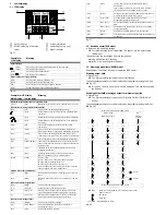
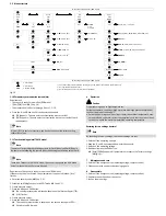

9
Fault clearance
Malfunction
Possible cause
Remedy
No display
No operating voltage or
impermissible operating voltage
Apply permissible operating
voltage
Electrical connections swapped
Connect the device in accordance
with the circuit diagram
Device defective
Replace device
Display or
switching output
does not react in
accordance with
the settings
Short circuit or overload at the
output
Eliminate short circuit or overload
Incorrect switching point taught
(e.g. at 0 bar)
Repeat teaching procedure
Device defective
Replace device
Parameter incorrect
Reset to factory settings
[Er_1] / [FAIL]
1)
Device defective
Replace device
[Er_2] / [ASIC]
1)
Device defective
Replace device
[Er10] / [OVER]
Measuring range exceeded
Comply with the measuring range
[Er20] / [tEMP]
2)
Temperature error
Check operating conditions
Replace device
[Er21] / [SHRt]
2)
Short circuit at OutA
Eliminate short circuit
[Er22] / [SHRt]
2)
Short circuit at OutB
Eliminate short circuit
[Err] / [BUSY]
OutA is switched active
Check device settings
[Err] / [ID]
Device ID error,
replication function failed
When replicating, use sensors with
the same type (same device ID)
[Err] / [COMM]
IO-Link communication error
Check the C/Q line
Check settings of the device sensor
1)
Display flashes red
2)
Display illuminated red
Fig. 21
10
Accessories
Accessories:
è
www.festo.com/catalogue
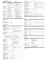
11
Technical data
SPAN-
General
Approval certificate
RCM
CE marking (
è
declaration of conformity)
In accordance with EU EMC directive
Note on materials
RoHS compliant
Input signal / measuring element
Operating medium
Compressed air in accordance with
ISO 8573-1:2010 [7:4:4]; inert gases, operation
with lubricated medium possible
Temperature of medium
[°C]
0 … +50
Ambient temperature
[°C]
0 … +50
Output, general
Accuracy
– P16
[% FS]
±2 at room temperature
– B2, B11, V1, P1, P2, P6, P10,
P025, P05, V025, V05, P12
[% FS]
±1.5 at room temperature
– B2, B11, V1, P1, P2, P6, P10
[% FS]
±3 in the entire temperature range
– P025, P05, V025, V05, P12,
P16
[% FS]
±4 in the entire temperature range
Repeat accuracy
[% FS]
±0.3 with Filt = OFF
Temperature coefficient
[% FS/K]
Typically 0.05
Switching output
Switching output
2x PNP or 2x NPN switchable
Switching function
Threshold value comparator
Window comparator
Auto difference monitoring
Switch-on/switch-off time
[ms]
typ.: 2, max.: 4 with FILT = OFF
Max. output current
[mA]
100
Capacitive load maximum DC
[nF]
100
Voltage drop
[V]
Max. 2
Pull-down / pull-up resistor
PNP: integrated; NPN: not integrated
Inductive protective circuit
Present
Analogue output
Output characteristic curve
initial value … end value
[V]
[V]
0 … 10
1 … 5
[mA]
4 … 20
Max. load resistance of current
output
[Ω]
500
Min. load resistance of voltage
output
[kΩ]
20
Output, additional data
Short circuit protection
Yes
Overload protection
Present
Electronics
Max. current consumption
[mA]
230
Nominal operating voltage DC
[V]
24
Operating voltage range DC
[V]
15 … 30
No-load supply current
[mA]
Max. 30
Ready-state delay
[ms]
typ. 80
1)
Protection against polarity reversal
All connections against each other
Mechanical system
Mounting position
Any, avoid condensation gathering in the sensor
Housing material
PA reinforced
Keyboard material
TPE-O
Threaded connections material
Brass (nickel-plated)
Display
Displayable units
bar, kPa, MPa, psi, mmHg, inchHg, inchH
2
O,
kgf/cm
2
Immissions / emissions
Storage temperature
[°C]
–20 … +80
Max. permissible relative air
humidity
[%RH]
85
Degree of protection (in
accordance with EN 60529)
IP40
Protection class (in accordance with DIN
VDE 0106-1)
III
Resistance to shocks (in accordance with
EN 60068-2)
30 g acceleration with 11 ms duration
(half-sine)
Vibration resistance (in accordance with
EN 60068-2)
10 … 60 Hz: 0.35 mm / 60 … 150 HZ: 5 g
1)
After this time, the electrical outputs take a defined, stable condition
Fig. 22
SPAN-
-B2
-B11
-V025
-V05
-V1
-P025
-P05
Pressure measuring
range
Start value
[bar]
[MPa]
-1
-0.1
0
0
Pressure measuring
range
End value
[bar]
[MPa]
1
0.1
10
1
-0.25
-0.025
-0.5
-0.05
-1
-0.1
0.25
0.025
0.5
0.05
Overload range
Start value
[bar]
[MPa]
-1
-0.1
Overload range
End value
[bar]
[MPa]
5
0.5
15
1.5
1
0.1
2
0.2
5
0.5
1
0.1
2
0.2
Fig. 23
SPAN-
-P1
-P2
-P6
-P10
-P12
-P16
Pressure measuring
range
Start value
[bar]
[MPa]
0
0
Pressure measuring
range
End value
[bar]
[MPa]
1
0.1
2
0.2
6
0.6
10
1
12
1.2
16
1.6
Overload range
Start value
[bar]
[MPa]
-1
-0.1
Overload range
End value
[bar]
[MPa]
5
0.5
6
0.6
15
1.5
20
2.0
Fig. 24
IO-Link
1)
Protocol version
Device V1.1
Profiles
Smart sensor profile
Function classes
Binary data channel (BDC)
Process data variable (PDV)
Identification
Diagnostics
Teach channel
Communication mode
COM2 (38.4 kBaud)
Port class
A
Process data width IN
2 byte
Process data content IN
2 bit BDC (pressure monitoring)
14 bit PDV (pressure reading)
IODD, IO-Link device description
è
www.festo.com/sp
1)
Only SPAN-...-PNLK-PNVBA
Fig. 25


