
1
2
3
p
Out
1
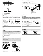
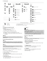
Reference value is determined
2
Measured value deviates by [d.SP] from the reference value
3
Monitoring area
Fig. 6
The parameters [SP.Lo], [SP.Hi], [t.Obs] and [d.SP] can be configured by the user.
The greater [t.Obs] is set, the more constant the pressure signal must be to establish
the reference value PRef.
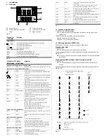
Function
NO (normally open)
NC (normally closed)
Switching function:
– 2 switching points (SP.Lo,
SP.Hi) for setting the valid
work range
– 1 switching point (d.SP)
for determination of
the monitoring area
TEACH mode
1)
:
– 2 teach-in points (TP1, TP2)
– TP1 = SP.Lo, TP2 = SP.Hi
SP.Lo P
Ref
SP.Hi
d.SP
1
0
Out
p
1
SP.Lo P
Ref
SP.Hi
d.SP
0
Out
p
1)
SP.Lo = smaller pressure value, SP.Hi = larger pressure value, independent of the Teach sequence
Fig. 7
4
Installation
Note
Installation and commissioning are to be carried out only by qualified personnel
in accordance with the operating instructions.
Remove all transport packaging. The material used in the packaging has been
specifically chosen for its recyclability.
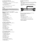
4.1 Mechanical and pneumatic
Note
An unfavourable mounting position can impair the function of the product.
Mount the sensor so that no condensate from the compressed air lines can
gather in the device.
Install the sensor so that it cannot be heated above the maximum permissible
operating temperature (plan for convection possibilities).
SPAN-...-G18M/R18M/N18M
Mounting bracket
– Seal connecting thread.
Max. 10 Nm
13 mm
Fig. 8
Example with G18M
Fig. 9
Example with SAMH-PU-A-. Fastening
SAMH-PN-W correspondingly
Front panel use SAMH-PN-F
– Size of the front panel cut-out in mm
è
Fig. 10.
– Fasten panel frame to the sensor.
– Guide sensor from the front into the cut-out on the front panel.
– Attach the clamping element and press until it catches.
31
-0.4
31
-0.4
X
31
-0.4
X=31*n+3.5*(n-1)
s=max. 5 mm
1
2
1
Panel frame
2
Clamping element
Fig. 10
Fig. 11
4.2 Electrical
Warning
Use only power sources which guarantee reliable electrical isolation of the oper
ating voltage in accordance with IEC/EN 60204-1. Consider also the general
requirements for PELV circuits in accordance with IEC/EN 60204-1.
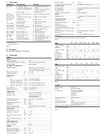
Connect sensor.
– Consider the maximum permissible line length: 30 m (20 m for IO-Link).
Pin
Colour
1)
Allocation
Plug L1
1
Brown (BN)
Operating v24 V DC
1 2 3 4
2
Black (BK)
Switching output OutA or IO-Link
(C/Q line)
3
White (WH)
Switching output OutB or
analogue output (pressure
signal InA)
4
Blue (BU)
0 V
1)
Colours apply for connecting cables
NEBS-L1... or electrical adapter SASC-P4... with NEBU-M8...
Fig. 12
Circuit diagrams
SPAN-...-PNLK-PNVBA
SPAN-...-PN-PN
Fig. 13
Fig. 14


