
5
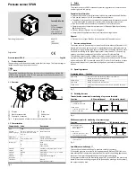
Commissioning
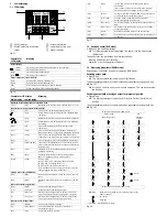
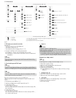
5.1 LCD display
1
3
2
1
4
5
1
Output display
2
Main display (e.g. measured
value)
3
Status information
4
Lower display (e.g. unit)
5
Signal indicator
Fig. 15
Example for
LCD display
Meaning
Output display
[OutA]
Switching output OutA selected (flashes with active IO-Link)
[OutA]
Switching output OutA set
[OutB]
Switching output OutB selected
[OutB]
Switching output OutB set
Status information / signal indicator
[Lock]
Security code activated (
è
Chap. 5.4)
[Spec]
Special menu selected (
è
Chap. 5.6)
[InA]
Pressure signal InA or analogue signal is selected
IIIIIIII
Graphic bar graph in the lower display [Sub.d]
Fig. 16
Example for LCD display
Meaning
Main display
Lower display
Measured value indicator and unit in the RUN mode
[– 0.53]
[bar]
Measured value indicator (here: negative value) and unit
Menu for the switching outputs (OutA and OutB)
[Edit]
[bin]
Edit menu for the switching outputs (binary)
[Fctn]
Determination of the switching function: threshold value
comparator
[Fctn]
Determination of the switching function: window comparator
d
[Fctn]
Determination of the switching function: auto difference
monitoring
[1.80]
[SP]
Value of switching point (only for threshold value
comparator)
[2.45]
[SP.Lo]
Value of lower switching point (window comparator);
lower limit of the work space (auto difference monitoring)
[6.45]
[SP.Hi]
Value of upper switching point (window comparator);
upper limit of the work space (auto difference monitoring)
[0.50]
[HY]
Value of hysteresis (not for auto difference monitoring)
[18]
[t.obS] / [MSEC]
Time interval for determination of a mean value, which is
used to determine the pressure change and establish the
reference value.
[0.25]
[d.SP]
Threshold value of the differential pressure with auto
difference monitoring
[NO]
[LOGC]
Switching characteristics of the switching outputs:
[NO] = normally open, [NC] = normally closed
[bLUE]
[COLR]
Display colour:
[bLUE] = Blue, colour change function deactivated
[R.ON] = Red, if switching output set
[R.OFF] = Red, if switching output not set
Note: Independent of the settings [COLR], the red colour
change appears with some malfunctions.
Extreme values (only SHOW mode)
[1.64]
[MIN]
Minimum measured pressure since switch-on or the last
reset
[8.50]
[MAX]
Maximum measured pressure since switch-on or the last
reset
Menu of the pressure signal (InA)
[Edit]
[ANLG]
Edit menu for the analogue output
[1 _ 5]
[Out] / [V]
Output function of the analogue output
[93]
[In.Hi] / [%]
Scaling of the analogue output in percent of the final
value of the pressure measuring range (FS - full scale)
[3]
[In.Lo] / [%]
Scaling of the analogue output in percent of the initial
value of the pressure measuring range (offset)
Menu for device settings (Spec)
[Edit]
[MENU]
Edit menu for additional settings
[16]
[Filt] / [MSEC]
Value of the filter time constant for the pressure
measurement signal
[bar]
[Unit]
Unit for the pressure indicator
[OFF]
[Z.AdJ]
[OFF] = zero point synchronisation (zero adjust)
deactivated
[ON] = offset correction for measured value indicator,
switching points and analogue output possible
[Unit]
[Sub.d]
Settings of the lower display in RUN mode: selected unit
or switching point of OutA or bar graph
[40]
[Eco] / [SEC]
Economy mode: period after which the display
background lighting is switched off
[PNP]
[bin] / [Out]
Shift of the switching outputs (binary) between PNP and
NPN
[bin]
[Pin3] / [Out]
Shift between switching output (binary) and analogue
output (lnA) at Pin3
[OFF]
[Code]
Activation and determination of the security code
[OFF]
[MASt]
Activation of the IO-Link master function for replication of
parameters
Fig. 17
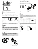
5.2 Switch on sensor (RUN mode)
Switch on the operating voltage.
è
Current measured value is displayed. The sensor is in the basic status
(RUN mode).
The basic status can be reached from other modes by:
– pressing edit button for 3 seconds
– expiration of a monitoring time (Timeout)
5.3 Displaying parameters (SHOW mode)
Requirement: The sensor is ready for operation (RUN mode).
Switching output OutA
Press A-key.
è
The first parameter set is displayed. [Fctn] flashes.
The subsequent parameters can be displayed by repeatedly pressing the A key
(
è
Fig. 18).
è
At the end, the min. and max. values are displayed. This can be reset with
the Edit key.
Switching output OutB or analogue output for pressure signal InA
Press B-key.
è
The first parameter set is displayed. [Fctn] with OutB or [Out] with InA
flashes.
The subsequent parameters can be displayed by repeatedly pressing the B-key
(
è
Fig. 18).
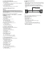
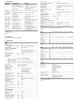
Measured value indicator (RUN mode)
OutA or OutB
InA
1)
(Switching output)
(Analogue
output)
_|¯
_|¯|_
d_|¯|_
Out
Fctn
Fctn
Fctn
SP
SP.Lo
SP.Lo
In.Hi
HY
SP.Hi
SP.Hi
In.Lo
HY
t.obS
d.SP
LOGC
LOGC
LOGC
COLR
COLR
COLR
MIN
MIN
MIN
Reset
MAX
MAX
MAX
Reset
Measured value indicator (RUN mode)
MIN, MAX:
Parameter is displayed only for switching output OutA,
without Timeout
Edit button
A or B key
1)
Only SPAN-...-PNLK-PNVBA; via B-key
Fig. 18


