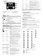
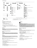

5.9 Menu structure
Measured value indicator (RUN mode)
2)
OutA
Edit
bin
OutB
Edit
bin
InA
Edit
ANLG
Spec
Edit
MENU
_|¯
Fctn
_|¯|_
Fctn
d_|¯|_
Fctn
Out
0…10 V
1…5 V
4…20 mA
Filt
OFF,
2,
4, 8, ... 1024 ms
SP
SP.Lo
SP.Lo
0…
60
…100 % FS
1)
In.Hi
10…
100
% FS
Unit
bar
, kPa, MPa, PSI, MMHG, inHG, iH20, kGF
SP.Hi
SP.Hi
0…
70
…100 % FS
1)
In.Lo
0
…90
% FS
Z.AdJ
OFF
, ON
3)
HY
HY
0…
0.5
…90 % FS
1)
Sub.d
Unit
, SP, SP.Lo, SP.Hi, d.SP, || || || ||
t.obS
5…
200
…9999 ms
Eco
di.ON,
5, 10, 20, 40, 80, 160, 320, 640 s
d.SP
0.5…
2
…50 % FS
1)
Out
bin
PNP
, NPN
LOGC
NO
, NC
Out
Pin3
bin,
ANLG
2)
COLR
bLUE
, R.OFF, R.ON
Lock Code
OFF
, 1…9999
MASt
OFF
, ON
Measured value indicator (RUN mode)
= Edit button
= A- or B-key
1)
The values refer to the respective measuring range. The display takes place in the selected unit.
2)
Not applicable with PN-PN variant
3)
Not valid with -B2 and -B11 variant (factory setting ON)
bold
= factory setting
Fig. 20
5.10 Zero point synchronisation (zero adjust)
Requirement:
– The sensor is ready for operation (RUN mode).
– [Z.AdJ] [ON] is set (
è
Chap. 5.6).
– The measured value lies in the range 0 bar ± 3 % FS.
Press the A- and B-key and Edit button simultaneously.
è
[OK] appears. The zero point synchronisation was successful.
è
[FAIL] appears. The zero point synchronisation was not successful. Check
requirements.
Note
If [Z.AdJ] [OFF] is set for a later time, the device takes over the factory setting
calibration values.
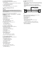
5.11 Teach switching points (TEACH mode)
Note
The process for teaching the switching outputs for OutA (A-key) and OutB (B-key) is
the same. In the following, the process is described using the switching output OutA.
Note
There is no Timeout in the TEACH mode. The sensor changes to the RUN mode
only after the entire teach process is ended.
Requirement: The sensor is ready for operation (RUN mode).
If the security code is activated, the parameter entry option is blocked: [Lock]
flashes.
Enter the security code (
è
Chap. 5.4).
1. Establish switching function in the EDIT mode (
è
Chap. 5.5).
2. Create pressure value 1.
3. Press the A-key and Edit button.
è
The current pressure value will then be adopted as the first teach point (TP1).
è
[t-IN] flashes.
4. Create pressure value 2.
5. Press the A-key and Edit button.
è
The current pressure value is adopted as the second teach point (TP2).
è
Switch to the RUN mode.
6
Operation
Caution
Property damage due to high temperatures.
Extreme pneumatic conditions (high cycle rate with large pressure amplitude)
can heat the product above 80° C.
Select the operating conditions (in particular the ambient temperature, pres
sure amplitude, cycle rate, current consumption) such that the product does
not heat up above the maximum permitted operating temperature.
Restoring factory settings (restore)
Note
By resetting to factory settings, the current settings are lost.
1. Switch off the operating voltage.
2. Keep the A- and B-keys pressed down simultaneously.
3. Switch on the operating voltage.
4. Additionally press the Edit button.
è
[Rsto] [PARM] appears. All parameters are reset to the factory settings
(
è
Fig. 20).
7
Maintenance and care
1. Switch off the energy sources (operating voltage, compressed air).
2. Clean sensor with non-abrasive cleaning agents.
8
Disassembly
1. Switch off the energy sources (operating voltage, compressed air).
2. Separate connections from the sensor.
3. Loosen the mountings.


