


The EDIT mode enables the following settings:
switching mode for OutA (air consumption [ConS] or flow [FLW] )
switching function (threshold−value or window comparator for OutA and OutB)
switching points [SP] for OutA and OutB
consumption switching impulse [CI] only for OutA in switching mode [ConS]
hysteresis [Hy] for OutA and OutB
switching element function [no/nc] for OutA and OutB
colour change of the display from blue to red for flow mode (for OutB).
Special menu with following settings:
changeover of the standard conditions via [Option] (OFF, 1, 2)
physical units for flow [FLW] (scfm, l/min)
analogue filter [AnA.F]
digital filter [dIG.F]
physical units for air consumption [ConS] (m
3
, scf, l)
switching output [nPn/PnP]
security code [Lock].
Starting EDIT mode
Warning
Depending on the functioning of the machine/system, manipulation of signal
states may cause serious personal injury.
· Note that if the switching status of the outputs is modified in the EDIT mode,
the new status will be effective immediately.
Various settings can be selected with the operating keys (A/B button):
switching output for which the behaviour is to be set
special menu.
1.
Press the Edit button.
The EDIT mode is active and [OutA] flashes or flashes when the security lock
is active [Lock].
2.
Press the A/B buttons until the chosen security code is set.
3.
Press the Edit button.
The EDIT mode is active and [OutA] flashes.
Setting switching behaviour of the switch outputs
Both switch outputs (OutA/OutB) can be set for flow measurement. Alternatively,
switching output OutA can be set for the accumulated air consumption measure
ment. The combination of accumulated air consumption measurement (OutA) and
flow measurement (OutB) is possible.
a) Setting switching function for flow measurement
Note
The process for setting the switch outputs is fundamentally the same. Addition
ally, the switching mode [FLW] must be selected for OutA, since OutA can also
be configured for air consumption measurement. For OutB, the colour change
for the display can also be set.
In the following, the process is described using the switching output OutA.
The SFAM is in EDIT mode and [OutA] is flashing,
start
è
section EDIT mode.
· To set OutA, proceed as follows:
1.
Press the Edit button to confirm the selection.
[FLW] or [ConS] flashes.
2.
Select the flow measurement (FLW) with the A/B buttons.
3.
Press the Edit button to confirm the selection.
The currently set switching function flashes.
4.
Select the desired switching function with the A/B buttons.
5.
Press the Edit button to confirm the selection.
[SP] or [SP.Lo] flashes.
6.
Set the switching point (SP or SP.Lo) with the A/B buttons.
7.
Press the Edit button to confirm the set value.
Only with Window comparator switching function.
[SP.Hi] flashes
· Set the value (SP.Hi) with the A/B buttons.
· Press the Edit button to confirm the set value.
[Hy] flashes.
8.
Set the value for the hysteresis (Hy) with the A/B buttons.
9.
Press the Edit button to confirm the set value.
[no] or [nc] flashes.
10. Select the switching element function (no/nc) with the A/B buttons.
11. Press the Edit button to confirm the set value.
The SFAM is in RUN mode.
Carry out a test run with various flows to ascertain whether the SFAM switches as
desired (switching points and hysteresis).
b) Setting switching function for air consumption measurement
The SFAM is in EDIT mode and [OutA] is flashing,
start
è
section EDIT mode.
1.
Press the Edit button to confirm the selection.
[FLW] or [ConS] flashes.
2.
Select the flow measurement (ConS) with the A/B buttons.
3.
Press the Edit button to confirm the selection.
[CI] flashes.
4.
Set the value for the consumption impulse (CI) with the A/B buttons.
5.
Press the Edit button to confirm the set value.
[no] or [nc] flashes.
6.
Select the switching element function (no/nc) with the A/B buttons.
7.
Press the Edit button to confirm the set value.
The SFAM is in RUN mode.
Carry out a test run with various flows to ascertain whether the SFAM switches as
desired (switching points and hysteresis).
Setting colour change (only for Out B)
With the SFAM, you can set a colour change in the display for the flow measure
ment at the output OutB dependent on the switching point. As a result, you can
visualise the equipment condition over a large distance. If the switching threshold
is exceeded or fallen below, the colour of the display changes. The following set
tings can be chosen:
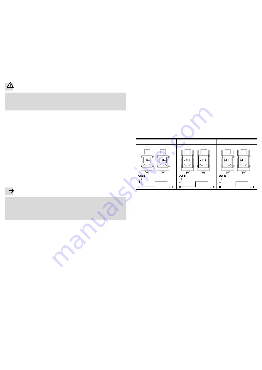
r.On =
Display is red when the switching output is High(1).
Display is blue when the switching output is Low(0).
r.OFF = Display is red when the switching output is Low(0).
Display is blue when the switching output is High(1).
bLUE = Display is blue; the function colour change is switched off.
Colour change
for r.ON
for r.OFF
with bLUE
blue
red
red
blue
blue
Fig.13
The SFAM is in EDIT mode and [OutA] is flashing,
start
è
section EDIT mode.
· To set the colour change, proceed as follows:
1.
Press the B button.
[Out B] flashes.
2.
Press the Edit button to confirm the selection.
3.
Press the Edit button several times until [rON], [rOFF] or [bLUE] flashes in the
display.
4.
Select the desired setting (rON, rOFF or bLUE) with the A/B buttons.
5.
Press the Edit button to confirm the selection.
The SFAM is in RUN mode.
Setting special menu [SPEC]
The following settings can be undertaken in the special menu:
standard conditions
physical units for flow [FLW] (scfm or l/min)
analogue filter [AnA.F] with filter time constants in ms
digital filter [dIG.F] with smoothing in 7 steps for display and switching output
physical units for air consumption (m
3
, scf or l)
set switching output [PnP] or [nPn]
removal of security blocking [Lock] with security code.
This is how you reach the special menu:
The SFAM is in EDIT mode and [OutA] is flashing,
start
è
section EDIT mode.
1.
Press the A or B button until the menu (SPEC) is selected.
[SPEC] flashes.
2.
Press the Edit button to confirm the selection.
[Option] flashes, the standard conditions (OFF, 1 or 2) can be set.


