SDE1−...
Festo SDE1−... 0511e English
42
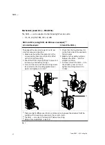
Mechanical/pneumatic(...−MS4/MS6)
The SDE1−... can be adapted to the following MS−series units:
DE, DL, EE, EM, FRM, LFR, LR, LRB
SDE1−G2−MS.. (using SDE1−G2−MS4 as an example)
1)
a) Install the adapter
b) Install the SDE1
2)
The adapter has two small spigots on its rear
side for pressure connection.
1. Make sure that either the spigot (a) or the
corresponding hole (b) on the unit is fitted
with an O−ring for sealing.
2. Check that the O−rings are firmly in place and
remove any unnecessary O−rings.
3. To mount the unit, push the mounting screws
(connected to the mounting brackets) out
wards and tighten to 0.5 Nm
3)
1. Check that the moulded seal (c)
on the front side of the adapter is
firmly in place.
2. Make sure the sealing surfaces
between the SDE1−... and the
adapter are clean.
3. To mount, insert the SDE1−... into
the adapter, press on it and
tighten mounting screw (d) to
1.0Nm.
a
b
d
c
1)
There are slight differences in form and dimensions between the adapters for MS4
and MS6. The mounting procedure is the same for both.
2)
The SDE1−... can also be rotated 180° before mounting.
3)
Using a Torx screwdriver size T10
Fig.7
Summary of Contents for SDE1 Series
Page 30: ...SDE1 Festo SDE1 0511e Deutsch 30 Bild 23 EDIT Modus ...
Page 32: ...SDE1 Festo SDE1 0511e Deutsch 32 Bild 24 TEACH Modus ...
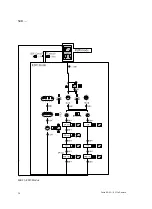
Page 60: ...SDE1 Festo SDE1 0511e English 60 Fig 23 EDIT mode ...
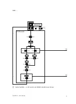
Page 62: ...SDE1 Festo SDE1 0511e English 62 Fig 24 TEACH mode ...
Page 63: ...SDE1 Festo SDE1 0511e 63 de Lochbilder Adapterplatte en Hole pattern on adapter plate ...


