Festo — CMMT-AS-...-S1 — 2021-04d
Installation
23
–
Only use permitted motor cables for the BR+/BR– connection.
–
If the diagnostic output of the safety sub-function concerned has to be evaluated: connect diag-
nostic output directly to the safety relay unit. Evaluation of the diagnostic output is either manda-
tory or optional depending on which safety classification is desired.
–
If diagnostic outputs are cross-wired for a device compound: wire diagnostic outputs as a ring. Run
the two ends of the ring to the safety relay unit and monitor for discrepancies.
Basic circuitry design
–
Safe sensors, e.g. emergency stop switches, light curtains, are routed to the safety relay unit (or the
safety PLC).
–
The safety relay unit requests the safety sub-functions on the servo drive via 2 channels and
evaluates the related feedback signals.
–
Connecting sensors, e.g. emergency stop switches, directly to the servo drive is not permitted,
because this means that the sensors are not monitored.
5.2
STO installation
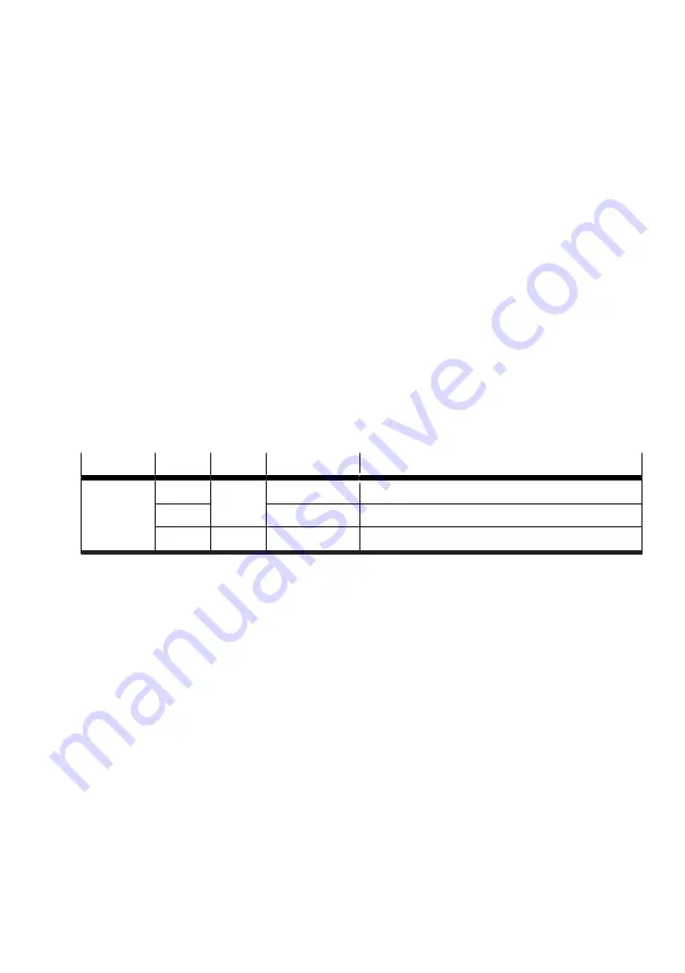
Inputs and outputs for the safety sub-function STO
The 2-channel request for the safety sub-function is made via the digital inputs #STO-A and #STO-B.
The STA diagnostic output indicates whether the safe status has been reached for the safety sub-func-
tion STO.
Connection Pin
Type
Identifier
Function
[X1A]
X1A.11
DIN
#STO-B
Safe torque off, channel B
X1A.12
#STO-A
Safe torque off, channel A
X1A.22
DOUT
STA
Safe torque off acknowledge
Tab. 8: Inputs and outputs for the safety sub-function STO
STO connection example
The safety sub-function STO (safe torque off) is triggered by an input device that makes the safety
request (e.g. light curtain).


