


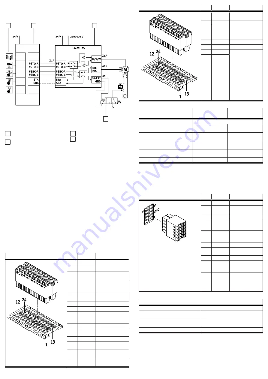
SBC connection example
The safety sub-function SBC (safe brake control) is triggered by an input device
that makes the safety request.
1
2
3
4
Fig. 9: SBC sample circuit
1 Input device for safety request
(e.g. light curtain)
2 Safety relay unit
3 Servo drive CMMT-AS
4 Control (here solenoid valve
example) of the clamping unit
Information on the sample circuit
The safety request is passed on to the servo drive on 2 channels via the inputs
#SBC-A and #SBC-B at the connection [X1A].
–
The request via the input #SBC-A switches off power to the signals BR+ and BR-
at the connection [X6B]. This de-energises and closes the holding brake.
–
The request via the input #SBC-B switches off power to the signal BR-EXT at the
connection [X1C]. This shuts off power to the control of the external clamping
unit. The clamping unit closes.
–
The safety relay unit monitors the SBA diagnostic output and checks whether
the safe status has been reached for the safety sub-function SBC.
7.8
Interfaces
Observe the requirements for mating plugs
è
Manual Assembly, Installation.
7.8.1
[X1A], inputs and outputs for the higher-order PLC
The I/O interface [X1A] is located on the top of the device. This interface offers
access to functional and safety-related inputs and outputs of the device. These
include, for example:
–
Digital inputs for 24 V level (PNP logic)
–
Digital outputs for 24 V level (PNP logic)
–
Signal contact for safety chain (RDY-C1, RDY-C2)
–
differential analogue input ±10 V control voltage
The inputs and outputs of this I/O interface are used for coupling to a higher-
order PLC. The safety-related inputs and outputs are connected to a safety relay
unit.
[X1A]
Pin
Function
Description
24
RDY-C1
Normally open contact:
ready for operation mes-
sage (Ready)
23
RDY-C2
22
STA
Diagnostic output Safe
torque off acknowledge
21
SBA
Diagnostic output Safe
brake control acknowl-
edge
20
–
reserved, do not connect
19
–
18
SIN4
Release brake request
17
GND
Reference potential
16
TRG0
fast output for triggering
external components,
channel 0
15
TRG1
like TRG0, but channel 1
14
CAP0
fast input for position
detection, channel 0
13
CAP1
like CAP0, but channel 1
12
#STO-A
Control input Safe torque
off, channel A
11
#STO-B
Control input Safe torque
off, channel B
10
#SBC-A
Control input Safe brake
control, channel A
[X1A]
Pin
Function
Description
9
#SBC-B
Control input Safe brake
control, channel B
8
–
reserved, do not connect
7
6
5
4
ERR-RST
Error acknowledgement
3
CTRL-EN
Power stage enable
2
AIN0
Differential analogue
input
1
#AIN0
Tab. 16: Inputs and outputs for the higher-order PLC with the CMMT-AS-...-S1
Requirements for the connecting
cable
Single device
Device compound
Shielding
Unshielded
Min. conductor cross section incl.
wire end sleeve with plastic sleeve
0.25 mm
2
–
Max. conductor cross section incl. plastic
wire end sleeve
0.75 mm
2
–
Min. conductor cross section incl. double
wire end sleeve with plastic sleeve
–
0.25 mm
2
Max. conductor cross section incl. double
wire end sleeve with plastic sleeve
–
0.5 mm
2
Max. length
3 m
0.5 m
Tab. 17: Requirements for the connecting cable
7.8.2
[X1C], inputs and outputs for the axis
The I/O interface [X1C] is located on the front of the device. This interface makes
functional and safety-related inputs and outputs available for components on the
axis. Output BR-EXT is used in conjunction with the safety sub-function Safe brake
control
è
Manual Safety sub-function.
[X1C]
Pin
Function
Description
10
GND
Reference potential
9
24V
Power supply output for
sensors
8
GND
Reference potential
7
LIM1
Digital input for limit
switch 1 (PNP logic,
24 V DC)
6
LIM0
Digital input for limit
switch 0 (PNP logic,
24 V DC)
5
GND
Reference potential
4
24 V
Power supply output for
sensors
3
–
reserved, do not connect
2
REF-A
Digital input for refer-
ence switch (PNP logic,
24 V DC)
1
BR-EXT
Output for connection of
an external clamping unit
(high-side switch, low
test pulses at #SBC-B are
transferred to BR-EXT)
Tab. 18: Inputs and outputs for the axis
Cable requirements
Shielding
unshielded/shielded
1)
Min. conductor cross section including wire end
sleeve with plastic sleeve
0.25 mm
2
Max. conductor cross section including wire end
sleeve with plastic sleeve
0.75 mm
2
Max. length
100 m
1) Use a shielded cable outside the control cabinet for safety engineering applications. Otherwise, a shield is
not absolutely essential, but is recommended.
Tab. 19: Cable requirements
Shield support requirements
Connecting the shield
1. On the device side, connect the cable shield to the shield clamp for the motor
cable.
2. On the machine side, connect the cable shield to an earthed machine part.


