1. Overview of components
1-13
Festo P.BE-CDVI-EN en 1202e
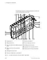
The following display and control elements can be found on
the valve side of the CDVI with DI connection “DeviceNet:”
1
2
3
4
5
6
1
Green LED PS “Power System,”
electronics operating voltage
2
Yellow LEDs, status display of the
solenoid coils
3
Manual overrides (per solenoid coil)
4
Green/red LED CP “Compact
Performance,” CP extension modules
5
Green/red LED MNS “Module/
Network Status”
6
Green LED PL “Power Load,” valve load
voltage
Fig. 1/3:
Display and control elements of the CDVI with DI connection “DeviceNet”
Summary of Contents for CDVI-DN
Page 2: ......
Page 4: ...Contents and general safety instructions II Festo P BE CDVI EN en 1202e...
Page 15: ...Overview of components 1 1 Festo P BE CDVI EN en 1202e Chapter 1 Overview of components...
Page 31: ...Assembly 2 1 Festo P BE CDVI EN en 1202e Chapter 2 Assembly...
Page 39: ...Installation 3 1 Festo P BE CDVI EN en 1202e Chapter 3 Installation...
Page 63: ...Commissioning 4 1 Festo P BE CDVI EN en 1202e Chapter 4 Commissioning...
Page 100: ...5 Cleaning maintenance and conversion 5 26 Festo P BE CDVI EN en 1202e...
Page 101: ...Technical appendix A 1 Festo P BE CDVI EN en 1202e Appendix A Technical appendix...
Page 109: ...A Technical appendix A 9 Festo P BE CDVI EN en 1202e A 2 Accessories www festo com catalogue...
Page 114: ...A Technical appendix A 14 Festo P BE CDVI EN en 1202e...
Page 115: ...Index B 1 Festo P BE CDVI EN en 1202e Appendix B Index...
Page 116: ...B Index B 2 Festo P BE CDVI EN en 1202e Contents B Index B 1...


