background image

1. Overview of components

1-10

Festo P.BE-CDVI-EN en 1202e

Ensure the protection class (see Appendix A “Technical
data”).

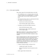
Via the left-hand end plate, the CDVI is supplied with com-
pressed air (connections (1), (12/14)), the exhaust air is
removed (connections (3/5), (82/84)) and with the CDVI-
MP the terminal is supplied with voltage.

Via the right-hand end plate the CDVI can also be sup-
plied with compressed air (connection (1)) and the ex-
haust air can be removed (connection (3/5)). The right-
hand end plate variant determines whether the CDVI is to
be operated with internal or external pilot air supply:

Right-hand end plate type CDVI5.0-EPR
for supplying the valves with internal pilot air,
branched from the overall supply (compressed air
channel (1)).

Right-hand end plate type CDVI5.0-EPR-S
for supplying the valves with external pilot air, pres-
sure regulated separately (3 ... 8 bar). The external
pilot air is supplied via connection (12/14) on the left-
hand end plate.

1.3.3

Valves

Note

The valve positions are intended for Festo valves and may
be fitted only with the valves approved of by Festo.

The valve positions must not be used for any other pur-
pose.

The components on the valve positions are marked with
identification codes. With these codes you can ascertain the
equipment fitted on your CDVI. The codes are printed on the
covers of the valves or on the blanking plate. An overview of
the valves can be found in Appendix A.

Summary of Contents for CDVI-DN

Page 1: ...Description of CDVI pneumatics Valve terminal type 15 Clean Design Type CDVI5 0 Description 197363 en 1202e 762312 Valve terminal CDVI...

Page 2: ......

Page 3: ...012 Internet http www festo com E mail service_international festo com The copying distribution and utilization of this document as well as the communication of its contents to others without expresse...

Page 4: ...Contents and general safety instructions II Festo P BE CDVI EN en 1202e...

Page 5: ...0 1 3 4 Connection display and control elements 1 12 2 Assembly 2 1 2 1 Mounting the valve terminal 2 4 2 1 1 Wall mounting 2 5 3 Installation 3 1 3 1 Compressed air preparation 3 4 3 1 1 Operation wi...

Page 6: ...valves 4 10 4 4 Troubleshooting 4 11 4 4 1 Impairment of function 4 11 4 4 2 Operating status of the pneumatic system 4 12 5 Cleaning maintenance and conversion 5 1 5 1 Cleaning the CDVI 5 4 5 2 Gener...

Page 7: ...n the documentation supplied with the product are permitted In perfect technical condition When used together with commercially available compo nents such as actuators the specified limits for pressur...

Page 8: ...ructions VI Festo P BE CDVI EN en 1202e Target group This manual is directed exclusively at technicians trained in control and automation technology Service Please consult your local Festo Service if...

Page 9: ...way mid position valves Manifold block Expansion block with 1 or 2 valve positions without additional supply Expansion block with 1 or 2 valve positions without additional pneumatic supply Expansion b...

Page 10: ...an be found in the appendix Notes on the electrical installation of the CDVI with multi pin plug connection can be found in the brief description of this valve terminal Instructions on the electrical...

Page 11: ...is made between the following danger warnings Warning means that failure to observe this instruction may result in serious personal injury or damage to property Caution means that failure to observe t...

Page 12: ...endations tips and references to other sources of information Accessories Information on necessary or useful accessories for the Festo product Environment Information on the environmentally friendly u...

Page 13: ...nsion blocks end plates valves and blanking plates DI connection Fieldbus direct This variant of the CDVI can be connected directly to the appropriate fieldbus e g DeviceNet End plate Blanking plate a...

Page 14: ...202e Term abbreviation Meaning Separator plate Sealing variant with open or closed supply ducts The variants with closed supply ducts serve to form pressure zones Tubing connection Connecting the supp...

Page 15: ...Overview of components 1 1 Festo P BE CDVI EN en 1202e Chapter 1 Overview of components...

Page 16: ...erview of components 1 1 1 1 The Clean Design valve terminal CDVI from Festo 1 4 1 2 Description of variants 1 5 1 3 Description of components 1 6 1 3 1 In line valve manifolds 1 7 1 3 2 End plates 1...

Page 17: ...Identification code of the pneumatic components Connection display and control elements Further information Information on the electrical components of the CDVI with MP connection can be found in the...

Page 18: ...wing advantages Easy to clean larger spaces between the valves no sharp edges no narrow radii no dirty corners Increased resistance to corrosion Resistance to acid and alkaline cleaning agents Complie...

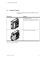
Page 19: ...s The CDVI is available with the following alternative electrical connections CDVI variant Remarks CDVI with MP connection With this CDVI the multi pin cable has already been fitted onto the valve ter...

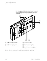
Page 20: ...matic connections 1 12 14 3 5 82 84 and on the CDVI MP with MP connection 2 Manifold block 4 or 8 valve positions 3 Optionally up to 8 expansion blocks possible with 1 valve position each 4 Right hand...

Page 21: ...eumatic supply connection and electrical power supply Both versions provide 1 or 2 valve positions A maximum of 8 Mo expansion blocks or 4 Bi expansion blocks can be mounted to one manifold block Mixe...

Page 22: ...creating further pressure zones 2 valve positions working lines pneum supply ports 2 valve positions working lines power supply1 2 valve positions working lines pneum ports and power supply1 1 valvle...

Page 23: ...n CDVI5 0 EB DZ Separating the compressed air channel 1 CDVI5 0 EB DZP Separating the exhaust duct 3 5 CDVI5 0 EB DZR Separating the compressed air channel and the exhaust duct CDVI5 0 EB DZPR End pla...

Page 24: ...te type CDVI5 0 EPR for supplying the valves with internal pilot air branched from the overall supply compressed air channel 1 Right hand end plate type CDVI5 0 EPR S for supplying the valves with ext...

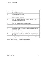
Page 25: ...table K Two 3 2 way valves monostable normal position closed M 5 2 way valve monostable N Two 3 2 way valves monostable open in normal position R 2 2 way valves monostable control side 14 closed in no...

Page 26: ...nd control elements The following display and control elements can be found on the valve side of the CDVI with MP connection 1 2 1 Yellow LEDs status display of the solenoid coils 2 Manual overrides p...

Page 27: ...4 5 6 1 Green LED PS Power System electronics operating voltage 2 Yellow LEDs status display of the solenoid coils 3 Manual overrides per solenoid coil 4 Green red LED CP Compact Performance CP exten...

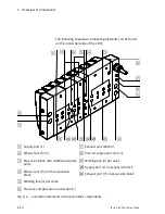
Page 28: ...1 Supply port 1 2 Exhaust port 3 5 3 Expansion block with additional supply ports 4 Exhaust port 5 on the expansion block 5 Working line 4 per valve 6 Pressure compensation connection L 7 Exhaust por...

Page 29: ...o P BE CDVI EN en 1202e The following electrical connection can be found on the connection side of the CDVI with MP connection 1 1 Electric multi pin plug connection Fig 1 5 Electrical connection elem...

Page 30: ...an be found on the connection side of the CDVI with DI connection DeviceNet 1 2 3 4 5 1 Fieldbus output socket M12 2 Fieldbus input plug M12 3 CP expansion M9 4 Power supply plug M12 5 Additional elec...

Page 31: ...Assembly 2 1 Festo P BE CDVI EN en 1202e Chapter 2 Assembly...

Page 32: ...2 Assembly 2 2 Festo P BE CDVI EN en 1202e Contents 2 Assembly 2 1 2 1 Mounting the valve terminal 2 4 2 1 1 Wall mounting 2 5...

Page 33: ...his chapter describes how to assemble the CDVI on a mounting surface Further information The CDVI is pre mounted when supplied by the plant If you wish to supplement or replace pneumatic components no...

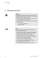
Page 34: ...he following The compressed air supply The power supply Note Handle all the components of the CDVI with great care Note especially the following Avoid an offset between the components otherwise the pr...

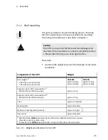
Page 35: ...Weight Basic weight 1 CDVI with 4 valve positions CDVI with 8 valve positions CDVI MP approx 1050 g approx 2090 g CDVI FB approx 1320 g approx 2360 g Expansion block with 1 valve position 2 With with...

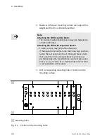
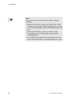
Page 36: ...pansion blocks 1 valve position may protrude unfastened If the expansion provides more than one valve position fasten the last expansion block However please note that a maximum of 4 valve positions m...

Page 37: ...shers The ter minal can be mounted in any desired position but the CDVI should be mounted so that dirt will be washed out during cleaning and the cleaning agent can drip off 1 2 3 1 Earthed mounting s...

Page 38: ...90 mm around the CDVI e g by means of mounting profiles or a section cut out of the mounting surface so that the tubing is not bent Make sure that there is a good conductive connec tion between the mo...

Page 39: ...Installation 3 1 Festo P BE CDVI EN en 1202e Chapter 3 Installation...

Page 40: ...eral instructions on installation 3 7 3 3 Laying the tubing 3 8 3 4 Notes on installing the CDVI 3 10 3 4 1 Pilot control of the solenoid coils pilot air supply 3 10 3 4 2 CDVI with pressure zone sepa...

Page 41: ...r supply Instructions on operating the valve terminal with pres sure zone separation Fitting the QS threaded connectors Connecting the power supply Earthing the CDVI Address assignment of the valves F...

Page 42: ...oils are used oils based on synthetic esters or nat ive esters e g rapeseed oil methylic ester the residual oil content must not exceed max 0 1 mg m3 see ISO 8573 1 class 2 If mineral oils are used e...

Page 43: ...ed compressed air must be used The compressed air prepared with the compressor must correspond in quality to unlubricated compressed air If poss ible do not operate the complete system with lubricated...

Page 44: ...from the lubricator 2 Ascertain the valve terminal which controls this cylinder 3 Remove the silencer if fitted from port 3 5 4 Hold a piece of white cardboard 10 cm in front of the ex haust port 5 L...

Page 45: ...roperty Before carrying out mounting installation and mainten ance work switch off the following Compressed air supply Operating and load voltage supplies Pay attention to the following The components...

Page 46: ...1 Push the tubing as far as possible into or over the tube coupling of the threaded connector 2 Tighten the clamping screw 1 or if applicable pull the locking ring 2 over the tube coupling 3 Seal con...

Page 47: ...atic tubing on the CDVI valve termin al Switch off the compressed air supply Make sure that all pneumatic tubing is pressureless Exhaust all actuators controlled by valves which are closed in normal o...

Page 48: ...The pilot air is supplied centrally to all valves of the CDVI Therefore operate the valve terminal either with intern ally branched or externally supplied pilot air This will ensure reliable operation...

Page 49: ...tuating operating pressure The external pilot air supply is supplied centrally for all solenoid coils via the pilot port 12 14 on the left end plate This also applies when the CDVI is operated with di...

Page 50: ...With internal pilot air supply and pressure zone separation of channel 1 observe the following The internal pilot air supply is branched in the right end plate from channel 1 The operating pressure in...

Page 51: ...CDVI MP CDVI FB Standard expansion block Type CDVI5 0 EB Type CDVI5 0 EB FB The position of the separator plate for pressure zone separation is between the manifold block and the expansion block 1 Se...

Page 52: ...ZV EP L and EP R optional EB ZV EP L End plate left EP R End plate right EB ZV Expansion block with additional supply Unused ports must be sealed Tab 3 2 Separator plates for creating 2 pressure zones...

Page 53: ...between the expansion blocks 1 Separator plate without channel separation 2 Separator plate with channel separation Pressure zone 2 3 5 1 1 2 1 Pressure zone 1 82 84 12 14 1 3 5 Pressure zone 3 5 1 3...

Page 54: ...Separator plate combinations for creating pressure zones 3 4 3 Operating the CDVI with vacuum low pressure Note The valves with ident code H K and N 2x3 2 way valves are not permitted for operation wi...

Page 55: ...code N K and H if supplied via port 1 are not suitable for vacuum low pressure Pressure zone with excess pressure supply 1 via port 1 The pressure zone can additionally be equipped with the following...

Page 56: ...cting the pneumatic lines In the case of connecting plates fitted with blanking plates seal the working lines 2 and 4 with blanking plugs or threaded blanking plugs to prevent dirt from entering For o...

Page 57: ...n blocks can be separated by means of a separate exhaust duct 3 5 Note Under certain circumstances excess pressure can build up under the valve covers of the CDVI This pressure is re duced via the pre...

Page 58: ...4 G 1 8 G 1 8 in the manifold block in the expansion block with auxiliary power supply Pilot air supply 12 14 G 1 8 in the left end plate Exhaust air 3 5 3 5 G 3 8 G 1 8 in the left right end plate i...

Page 59: ...r 82 84 can lead to functional impairments of the CDVI Use non return valves in the common exhaust lines 3 5 and 82 84 Valve terminal Valve terminal Common 3 5 Common 82 84 Common 3 5 Common 3 5 Syste...

Page 60: ...dance with IEC DIN EN 60204 1 electrical equipment of machines general requirements Note Check within the framework of your EMERGENCY STOP circuit to ascertain the measures necessary for putting your...

Page 61: ...ection between the CDVI and the earth potential 3 6 Address assignment of the valves Detailed instructions on addressing CDVI with DI connection DeviceNet can be found in the electronics manual P BE C...

Page 62: ...iagram shows the addressing sequence using the example of the CDVI with 9 valve positions 0 1 2 3 4 5 6 7 8 9 10 11 12 13 14 15 1214 1214 1214 1214 1214 14 1214 4 3 2 1 5 6 7 1 4 valve manifold block...

Page 63: ...Commissioning 4 1 Festo P BE CDVI EN en 1202e Chapter 4 Commissioning...

Page 64: ...re commissioning 4 4 4 1 2 Pressure increase in the overall supply 4 4 4 2 Checking the valves and the valve actuator combination 4 6 4 2 1 Manual override 4 6 4 2 2 Checking 4 7 4 3 LED displays of t...

Page 65: ...following Instructions on building up pressure in the overall supply Checking the valves and the valve actuator combination The function of the manual overrides Troubleshooting Assignment of the LEDs...

Page 66: ...noid coil is constantly under stress Please observe the following instructions on building up pressure in the overall supply 4 1 2 Pressure increase in the overall supply Warning If the pressure build...

Page 67: ...an electric signal The gradual pressure build up of the overall supply does not affect the actuator in that case The actuator would react suddenly e g a cylinder would extend or retract suddenly depe...

Page 68: ...slow start up pressurisation 4 2 Checking the valves and the valve actuator combination 4 2 1 Manual override You should use the manual override especially when commis sioning the pneumatic system in...

Page 69: ...s is as follows 1 MO for solenoid coil 14 2 MO for solenoid coil 12 1 2 Fig 4 2 Position of the manual overrides 4 2 2 Checking Note Before commissioning the CDVI note the specifications on the medium...

Page 70: ...perform sudden unexpected movements which may cause personal injury and material damage Disconnect the operating voltage supply for the solenoid coils from the relevant connections on the valve termin...

Page 71: ...position by actuation of the manual override The electric signal is dominant in this case Reset the electric signal before actuating the manual override 1 Switch on the compressed air supply 2 Check...

Page 72: ...g 4 3 Assignment of the LED and MO to the solenoid coil LED Switching posi tion of the valve Meaning possible cause if the valve does not switch Dark Normal position Logical 0 signal not applied lLght...

Page 73: ...r flows out between the modules Normal position After switching on again regulate the external pilot air to 3 8 bar Pressure drop or resonance noises Normal position Fitting the CDVI directly onto the...

Page 74: ...pressure zones Limiting the pressure zones on both sides by means of separator plates Subsequent conversion possible see chapter 5 Vacuum operation low pressure operation Separately supplied regulated...

Page 75: ...Cleaning maintenance and conversion 5 1 Festo P BE CDVI EN en 1202e Chapter 5 Cleaning maintenance and conversion...

Page 76: ...ning the CDVI 5 4 5 2 General preventive action 5 6 5 3 Dismantling fitting the CDVI 5 8 5 4 Replacing valve terminal components 5 9 5 4 1 Valves and blanking plates 5 9 5 5 Extension and conversion o...

Page 77: ...acing valve plates or blanking plates Adding valve positions Adding pressure zones Fitting and removing the end plates Additional information Instructions on connecting the electric components of the...

Page 78: ...ses see Appen dix A Technical data Easy to clean Caution Disinfectants may contain substances which can damage the components of the CDVI in the long or short term e g sodium hypochlorite Avoid using...

Page 79: ...leaning agent in the concentration at the processing temperature and in an environmentally friendly manner ac cording to the specifications of the manufacturer see data sheet but not at a processing t...

Page 80: ...can cause injury to persons and or damage to property Make sure that the higher order controller has not sent control signals to the solenoid coils Before carrying out conversion work on the CDVI swit...

Page 81: ...nts otherwise the protection class requirements may no longer be fulfilled see Appendix A Technical data Check the seals for damage before fitting IP 65 Make sure that the connecting surfaces are clea...

Page 82: ...tion port L and at the exhaust ports 3 5 82 84 see chapter 3 2 General connection technology 3 Disconnect the electrical connections CDVI with MP connection Loosen the electric multi pin by removing t...

Page 83: ...es of the in line manifolds are clean 2 Undo the mounting screws of the components see Fig 5 1 Pay attention to the O rings used as locking agent 3 Carefully pull the component off the in line valve m...

Page 84: ...5 Cleaning maintenance and conversion 5 10 Festo P BE CDVI EN en 1202e 1 In line manifold block 2 Valve 1 2 Fig 5 1 Assembling removing valves...

Page 85: ...ansion blocks are per missible In the extension at the most 8 solenoid coils can be triggered You can extend the CDVI by maximum 4 valve positions when using exclusively Bi expan sion blocks or by 8 v...

Page 86: ...dard expansion block for the pressure zone on the outside right EB1 MP or EB2 MP EB1 DN or EB2 DN EB1Z DN or EB2Z DN per internal pressure zone one expansion block with additional pneumatic supply cod...

Page 87: ...plates 4 Place a separator plate if necessary with pressure zone separation see section 5 5 3 Pressure zones onto the guide sleeves of the expansion block 5 Place the expansion block next to the mani...

Page 88: ...5 2 Adding valve positions on the CDVI without pressure zones 8 Fit the CDVI see section 5 3 5 5 2 Pilot air supply By fitting the appropriate right hand end plate you can oper ate your CDVI with inte...

Page 89: ...internal or external pilot air supply To facilitate mounting the end plate Festo recommends that you dismantle the CDVI from its mounting surface If the CDVI is easily accessible conversion of the en...

Page 90: ...ocked CDVI5 0 EB DZP CDVI5 0 EB DZR CDVI5 0 EB DZPR One or two expansion blocks See this chapter Tab 5 1 possibly blanking plug For ports 1 or 3 5 For ports 12 14 82 84 or 2 4 CDVI5 0 B G3 8 CDVI5 0 B...

Page 91: ...s of the separator plate type CDVI5 0 EB DZPR At a common position by means of the separator plate type CDVI5 0 EB DZP and at a further position by means of the separator plate type CDVI5 0 EB DZR 1 R...

Page 92: ...202e 1 2 3 4 5 6 1 Manifold block 2 Separator plate with channel separation 3 Standard expansion block 4 Separator plate without channel separation 5 Guide sleeves 6 Right hand end plate Fig 5 3 Examp...

Page 93: ...th channel separation for the second pressure zone into the guide sleeves of the expansion block with additional supply first expansion block see Fig 5 4 3 Place the expansion block with additional su...

Page 94: ...arator plate with channel separation 3 Expansion block with additional supply first expansion block 4 Standard expansion block second expansion block 5 Separator plate without channel separation 6 Gui...

Page 95: ...left hand end plate Remove the end plate to detach the multi pin plug from the CDVI Disassembly 1 Please observe the general preventive action see section 5 2 2 Release the left hand end plate on the...

Page 96: ...separator plate without channel separation onto the guide sleeves of the left hand end plate Note Make sure that the seal is seated correctly see Fig 5 5 2 First align the end plate so that the multi...

Page 97: ...e the general preventive action see section 5 2 2 Release the left hand end plate on the CDVI by unscrewing by one turn the two M5 mounting screws on the left hand end plate see Fig 5 6 3 Then unscrew...

Page 98: ...hand end plate on the manifold block 3 Tighten the end plate at first by hand so that the separ ator plate lies evenly on the manifold block and on the end plate 4 Tighten the screws with 3 5 Nm 0 5...

Page 99: ...nsion block Make sure that the separator plate s is are seated correctly between the components In this way you can ensure that the requirements of the protection classes see Appendix A Technical data...

Page 100: ...5 Cleaning maintenance and conversion 5 26 Festo P BE CDVI EN en 1202e...

Page 101: ...Technical appendix A 1 Festo P BE CDVI EN en 1202e Appendix A Technical appendix...

Page 102: ...A Technical appendix A 2 Festo P BE CDVI EN en 1202e Contents A Technical appendix A 1 A 1 Technical data A 3 A 2 Accessories A 9 A 3 Overview of the valves for the CDVI A 10...

Page 103: ...pply Valve Left right end plate Separator plate Cover Connecting cable Spacer bolt approx 1050 g approx 2090 g approx 255 g approx 510 g approx 210 g item approx 120 g item approx 30 40 g item approx...

Page 104: ...alve manifold End plate on in line valve manifold Pneumatic fitting blanking plug M6 and G 1 8 G 3 8 Spacer bolt on in line valve manifolds 0 8 Nm 0 1 Nm 3 5 Nm 0 5 Nm 1 0 Nm 0 5 Nm 5 0 Nm 1 0 Nm 10 N...

Page 105: ...icated operation possible required during subsequent operation Oil Viscosity class ISO VG32 according to DIN 51524 2 2006 04 Operating pressure pilot pres sure With internal pilot air supply Operating...

Page 106: ...Fig A 1 Diagram Control pressure depending on the operating pressure for 2x3 2 way valves with ident code H N and K Pneumatics Manual override of the valves non detenting Valve response times in ms I...

Page 107: ...2 way valves 3 2 way valves 3 2 way valves 5 2 way monostable or bistable 5 3 way mid position valve closed 5 3 way mid position valve exhausted 5 3 way mid position valve pressurized R S K N and H X...

Page 108: ...4 V ms on CDVI with expansion block Residual ripple 4 Vss Switch on current consumption high current phase Duration of high current phase typ 100 ms typ 30 ms typ 100 ms 3 per solenoid coil at 24 V w...

Page 109: ...A Technical appendix A 9 Festo P BE CDVI EN en 1202e A 2 Accessories www festo com catalogue...

Page 110: ...spring return no pressure supply via port 1 External vacuum compressed air supply via port 2 12 14 82 84 4 2 Ident code S Function a monostable 2 2 way valve normally open Pneumatic spring return no...

Page 111: ...14 2 4 14 5 Ident code W Function One 3 2 way valve monostable normal posi tion open external compressed air supply no pressure supply via port 1 External vacuum compressed air supply via port 2 82 84...

Page 112: ...d outputs In the case of the MP connection this valve occu pies 2 addresses on valve positions which sup port triggering 2 coils and 1 address on valve positions which support triggering 1 coil 82 84...

Page 113: ...3 way valve open in mid position 82 84 12 14 5 3 1 4 2 12 14 Ident code G Function 5 3 way valve closed in mid position 82 84 12 14 5 3 1 4 2 12 14 Ident code E Function 5 3 way valve mid position ex...

Page 114: ...A Technical appendix A 14 Festo P BE CDVI EN en 1202e...

Page 115: ...Index B 1 Festo P BE CDVI EN en 1202e Appendix B Index...

Page 116: ...B Index B 2 Festo P BE CDVI EN en 1202e Contents B Index B 1...

Page 117: ...aning the CDVI 5 4 Common lines 3 21 Components Description 1 12 1 13 1 14 1 15 Identification code 1 11 Overview 1 6 1 9 Tightening torques A 4 Weight 2 5 Weights A 3 Compressed air requirements 3 4...

Page 118: ...splay elements 1 12 1 13 E Earthing the CDVI 2 8 Electromagnetic compatibility A 8 EMERGENCY STOP 4 12 End plates 1 9 Installation 5 21 5 24 Exhaust air Centralised 3 21 Expansion block Installation 5...

Page 119: ...e of this manual VII O Operating pressure A 5 Operating status 4 11 4 12 P Pictograms X Pilot air supply 1 10 3 10 5 14 branched internally 3 10 Pilot pressure A 5 Diagram A 6 Ports Code 3 20 Position...

Page 120: ...6 Protection class A 4 S Separator plates 3 12 5 16 Service VI Slow start up pressurization 4 12 Spacer bolt 2 7 Standard nominal flow rates A 7 Start up pressurisation 4 6 Switch on current consumpti...

Page 121: ...B Index B 7 Festo P BE CDVI EN en 1202e V Vacuum 3 16 Vacuum operation 4 12 Valve response times A 6 Valves 1 10 A 10 Identification code 1 10 1 11 Overview 1 9 Vibration A 4 Voltage A 8...

Page 122: ...B Index B 8 Festo P BE CDVI EN en 1202e...

Reviews: