


2. Fitting
2-7
Festo P.BE-MPA-EN en 1108e
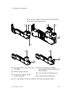
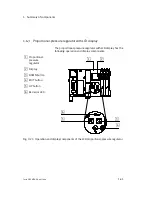
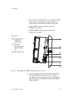
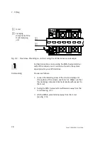
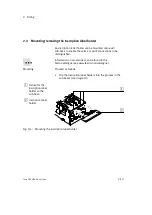
3. Mount the H-rail clamping units at all required mounting
points (see Tab. 2/2). Make sure that the clamping
component lies horizontally with respect to the H-rail.
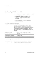
4. Hang the MPA-S valve terminal onto the H-rail
(see Fig. 2/1, arrow A).
5. Swing the MPA-S valve terminal onto the H-rail
(see Fig. 2/1, arrow B).
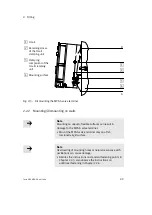
1
H-rail
2
Retaining screw
of the H-rail
clamping unit
3
Clamping
component of the
H-rail clamping
unit
4
Mounting surface
(A)
(B)
1
2
3
4
Fig. 2/1:
Mounting of the MPA-S valve terminal on an H-rail
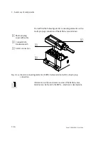
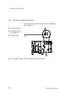
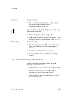
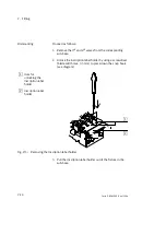
6. Turn the clamping components for mechanical locking
vertically behind the H-rail (see Fig. 2/2, arrow A);
then tighten the retaining screws of the H-rail clamping
with 1.3 Nm to secure the MPA-S valve terminal against
tilting or sliding.
Summary of Contents for 530411
Page 2: ......
Page 4: ...Contents and general instructions II Festo P BE MPA EN en 1108e ...
Page 16: ...Contents and general instructions XIV Festo P BE MPA EN en 1108e ...
Page 17: ...Summary of components 1 1 Festo P BE MPA EN en 1108e Chapter 1 Summary of components ...
Page 59: ...Fitting 2 1 Festo P BE MPA EN en 1108e Chapter 2 Fitting ...
Page 73: ...Installation 3 1 Festo P BE MPA EN en 1108e Chapter 3 Installation ...
Page 108: ...3 Installation 3 36 Festo P BE MPA EN en 1108e ...
Page 109: ...Commissioning 4 1 Festo P BE MPA EN en 1108e Chapter 4 Commissioning ...
Page 172: ...5 Maintenance and conversion 5 42 Festo P BE MPA EN en 1108e ...
Page 173: ...Technical appendix A 1 Festo P BE MPA EN en 1108e Appendix A Technical appendix ...
Page 209: ...Index C 1 Festo P BE MPA EN en 1108e Appendix C Index ...
Page 210: ...C Index C 2 Festo P BE MPA EN en 1108e Contents C Index C 1 ...


