43
SUN M20 - M30
GB
KodL MNOOPPQO - RevL SS - TQUQSTQ
Burner lighting
Switch on the power, operating the main switch ahead of the burner.
Open the manual gas valves and supply an adequate pressure to ensure closing of the gas pressure
switch.
Reset the unit (by pressing the red button).
Operation starts according to the diagram of fig. 11.
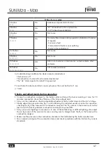
Operation sequence
1
The servomotor SA goes to the 2nd stage position, then the motor starts operating, turning the
fan and generating a ventilation called "washing" of the combustion chamber.
2
The air pressure switch closes, the servomotor goes to the 1st stage.
3
The ignition transformer starts its electric discharge, the gas valve opens and a flame is
produced.
4
The ionisation electrode detects the flame within the safety time and checks its stability. Combustion
continues until completion towards the required power, maintaining the set air/gas ratio.
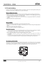
3.2 Commissioning
Checks to be made at first lighting, and after all maintenance operations involving disconnecting from
the systems or any work on safety devices or parts of the burner:
Before lighting the burner
Make sure the burner is correctly fixed in the boiler with the preliminary settings indicated above.
Make sure the boiler and system are filled with water or diathermic oil, the plumbing circuit valves
are open and that the flue is free and correctly sized.
Check the closing of the boiler door, so that the flame is only generated inside the combustion
chamber.
Open the gate valves along the gas pipe.
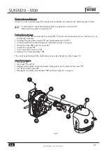
Air pressure switch setting
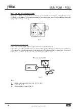
The purpose of the air pressure switch is to make the burner safe or shut it down in case of no combustion
air pressure. It must be set approximately 15% lower than the air pressure at the burner when this is at
nominal delivery with operation at 1st flame, checking that the CO value remains below 1%.
fig. 8

