background image

ECONCEPT ST

35

EN

cod. 3540S814  -  

/201

  (Rev. 00)

EN

1. GENERAL INSTRUCTIONS

Carefully read the instructions contained in this instruction booklet.

After boiler installation, inform the user regarding its operation and give him this
manual, which is an integral and essential part of the product and must be kept with
care for future reference.

Installation and maintenance must be carried out by professionally qualified person-
nel, according to current regulations and the manufacturer's instructions. Do not car-
ry out any operation on the sealed control parts.

Incorrect installation or inadequate maintenance can result in damage or injury. The
Manufacturer declines any liability for damage due to errors in installation and use
or failure to follow the instructions.

Before carrying out any cleaning or maintenance operation, disconnect the unit from
the power supply using the system switch and/or the special cut-off devices.

In case of a fault and/or poor operation, deactivate the unit and do not attempt to repair
it or directly intervene. Contact professionally qualified personnel. Repair/replacement of
the products must only be carried out by professionally qualified using original spare
parts. Failure to comply with the above could affect the safety of the unit.

This unit must only be used for its intended purpose. Any other use is considered
improper and therefore dangerous.

The packing materials are potentially hazardous and must not be left within the
reach of children.

The images given in this manual are a simplified representation of the product. In
this representation there may be slight and insignificant differences with respect to
the product supplied.

2. OPERATING INSTRUCTIONS

2.1 Introduction

Dear Customer,

Thank you for choosing 

ECONCEPT ST

, a wall-mounted boiler featuring 

FERROLI

ad-

vanced design, cutting-edge technology, high reliability and quality construction. Please
read this manual carefully since it provides important information on safe installation, use
and maintenance.

ECONCEPT ST

 is a high-efficiency, low emissions, sealed chamber, 

premix condens-

ing

 heat generator for heating and hot water production, running on natural gas or LPG

and equipped with a microprocessor control system.

The 

boiler shell

 consists of an aluminium lamellar exchanger and a ceramic 

premix

burner

 equipped with electronic ignition and ionisation flame control, modulating speed

fan and modulating gas valve. Domestic hot water production occurs through a special
stratification storage tank.

2.2 Control panel

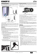
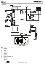
fig. 1  - Control panel

Key

1 =

DHW temperature setting decrease button

2 =

DHW temperature setting increase button

3 =

Heating system temperature setting decrease button

4 =

Heating system temperature setting increase button

5 =

Display

6 =

Summer / Winter mode selection button

7 =

Economy / Comfort mode selection button

8 =

Reset / filling button

9 =

Unit On / Off button

10 =

Sliding Temperature" menu button

11 =

Set DHW temperature reached

12 =

DHW symbol

13 =

DHW mode

14 =

DHW outlet temperature / setting (blinking during "Exchanger protection" func-
tion)

15 =

Eco (Economy) or Comfort mode

16 =

Outside sensor temperature (with optional outside sensor)

17 =

Appears on connecting the outside Sensor or the Remote Timer Control (op-
tionals)

18 =

Room temperature (with optional Remote Timer Control)

19 =

Burner lit and actual power (blinking during "Flame protection" function)

20 =

Antifreeze operation

21 =

Heating system pressure

22 =

Fault

23 =

Heating delivery temperature / setting (blinking during "Exchanger protection"
function)

24 =

Heating symbol

25 =

Heating mode

26 =

Set heating delivery temperature reached

27 =

Summer mode

Indication during operation

Heating

A heating demand (generated by the Room Thermostat or Remote Timer Control) is in-
dicated by flashing of the hot air above the radiator (details 24 and 25 - fig. 1).

The display (detail 23 - fig. 1) shows the actual heating delivery temperature and, during
heating standby time, the message 

"d2"

.

The heating graduation marks (detail 26 - fig. 1) light up as the heating sensor tempera-
ture reaches the set value.

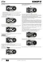
fig. 2

Domestic hot water (DHW)

A hot water tank heating demand is indicated by flashing of the hot water under the tap
(details 12 and 13 - fig. 1).

The display (detail 14 - fig. 1) shows the actual hot water outlet temperature and, during
DHW standby time, the message 

"d1"

.

The DHW graduation marks (detail 11 - fig. 1) light up as the hot water tank sensor tem-
perature reaches the set value.

fig. 3

Exclude hot water  storage tank (economy)

Hot water storage tank temperature  maintaining/heating can be excluded by the user. If
excluded, domestic  hot water will not be delivered.

When hot water tank  heating is activated (default setting), the COMFORT symbol (detail
15 - fig. 1) is activated on the display, and when off, the ECO symbol (detail 15 -  ) is
activated fig. 1on the display.

The hot water tank can be deactivated by the user (ECO  mode) by pressing the 

eco/

comfort

 button (detail 7 - fig. 1). To activate the  COMFORT mode, 

press the 

eco/com-

fort  button (detail 7 - fig. 1) again.

2.3 Lighting and turning off

Boiler not electrically powered

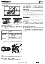
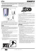
fig. 4 - Boiler not electrically powered

B

The antifreeze system does not work when the power and/or gas to the unit are
turned off. To avoid damage caused by freezing during long idle periods in win-
ter, it is advisable to drain all water from the boiler, DHW circuit and system; or
drain just the DHW circuit and add a suitable antifreeze to the heating system,
complying with that prescribed in sec. 3.3.

eco

comfort

m

o

de

r e s e t

ecomfort

bar

5

7

9

10

2

1

8

6

4

3

12

14

11

13

15

16

17

18

20

21

22

23

25

24

26

27

19

eco

comfort

m

o

de

r e s e t

eco

bar

eco

comfort

m

o

de

r e s e t

eco

bar

eco

comfort

m

o

de

r e s e t

bar

eco

comfort

m

o

de

r e s e t

 comfort

bar

 comfort

eco

comfort

m

o

de

r e s e t

Summary of Contents for ECONCEPT ST 25

Page 1: ... 5 E D C B F A D E F A B C E D C B A ISTRUZIONE PER L USO L INSTALLAZIONE E LA MANUTENZIONE INSTRUCCIONES DE USO INSTALACIÓN Y MANTENIMIENTO KULLANMA KURULUM VE BAKøM TALIMATLARø INSTRUCTIONS FOR USE INSTALLATION AND MAINTENANCE INSTRUCTIONS D UTILISATION D INSTALLATION ET D ENTRETIEN INSTRUCğIUNI DE UTILIZARE INSTALARE ùI ÎNTRETINERE ȱɇɋɌɊɍɄɐȱə Ɂ ȿɄɋɉɅɍȺɌȺɐȱȲ ɆɈɇɌȺɀɍ ɌȺ ɈȻɋɅɍȽɈȼɍȼȺɇɇə ...

Page 2: ...ra impianto riscaldamento 5 Display 6 Tasto selezione modalità Estate Inverno 7 Tasto selezione modalità Economy Comfort 8 Tasto Ripristino caricamento impianto 9 Tasto accensione spegnimento apparecchio 10 Tasto menù Temperatura Scorrevole 11 Indicazione raggiungimento temperatura acqua calda sanitaria impostata 12 Simbolo acqua calda sanitaria 13 Indicazione funzionamento sanitario 14 Impostazio...

Page 3: ...do remoto la temperatura ambiente desiderata all inter no dei locali La caldaia regolerà l acqua impianto in funzione della temperatura ambien te richiesta Per quanto riguarda il funzionamento con cronocomando remoto fare riferimento al relativo manuale d uso Temperatura scorrevole Quando viene installata la sonda esterna opzionale sul display del pannello comandi part 5 fig 1 è visualizzata l att...

Page 4: ...ve essere previsto lo spazio per lo smontaggio della mantellatura e per le normali attività di manutenzione 3 3 Collegamenti idraulici Avvertenze La potenzialità termica dell apparecchio va stabilita preliminarmente con un calcolo del fabbisogno di calore dell edificio secondo le norme vigenti L impianto deve essere cor redato di tutti i componenti per un correto e regolare funzionamento Si consig...

Page 5: ...i Il diametro del tubo gas che esce dalla caldaia non è determinante per la scelta del diametro del tubo tra l apparecchio ed il contatore esso deve essere scelto in funzione della sua lun ghezza e delle perdite di carico in conformità alla normativa in vigore B Non utilizzare i tubi del gas come messa a terra di apparecchi elettrici 3 5 Collegamenti elettrici Collegamento alla rete elettrica B La...

Page 6: ...na curva 90 1 metro orizzontale ha una lunghezza tot equivalente di 2 metri Tabella 2 Massima lunghezza condotti coassiali Collegamento con tubi separati fig 21 Esempi di collegamento con tubi separati Aria Fumi Per il collegamento dei condotti separati montare sull apparecchio il seguente accesso rio di partenza fig 22 Accessorio di partenza per condotti separati Prima di procedere con l installa...

Page 7: ...art 3 e 4 fig 1 per aumentare o diminuire la potenza Minima 0 Massima 100 Premendo il tasto sanitario part 1 fig 1 la potenza della caldaia viene regolata immediatamente al minimo 0 Premendo il tasto sanitario part 2 fig 1 la po tenza della caldaia viene regolata immediatamente al massimo 100 Nel caso in cui sia attiva la modalità TEST e vi sia un prelievo d acqua calda sanitaria sufficiente ad at...

Page 8: ...e e privo di incrostazioni Valvola gas difettosa Verificare e sostituire la valvola a gas Pressione gas di rete insuffi ciente Verificare la pressione del gas di rete Sifone ostruito Verificare ed eventualmente pulire il sifone A02 Segnalefiammapresente con bruciatore spento Anomalia elettrodo Verificare il cablaggio dell elettrodo di ionizzazione Anomalia scheda Verificare la scheda A03 Intervent...

Page 9: ...130 Circolatore sanitario 138 Sonda esterna 139 Cronocomando remoto 145 Idrometro 154 Tubo scarico condensa 155 Sonda temperatura bollitore 161 Scambitore di calore a condensa 186 Sensore di ritorno 188 Elettrodo d accensione 193 Sifone 194 Scambiatore sanitario 195 Accumulo 196 Bacinella condensa 201 Camera miscelazione 209 Mandata bollitore 210 Ritorno bollitore 241 By pass automatico 243 Sonda ...

Page 10: ...as alimentazione G31 mbar 37 37 CO2 max G31 10 10 CO2 min G31 9 5 9 5 Portata gas max G31 kg h 2 11 2 73 Portata gas min G31 kg h 0 41 0 51 Classe efficienza direttiva 92 42 EEC Classe di emissione NOx 5 5 NOx Temperatura fumi max 80 C 60 C C 65 65 Temperatura fumi min 80 C 60 C C 60 60 Temperatura fumi max 50 C 30 C C 46 46 Temperatura fumi min 50 C 30 C C 31 31 Portata fumi max kg h 41 2 58 6 Po...

Page 11: ...ola deviatrice 130 Circolatore bollitore 138 Sonda esterna 139 Cronocomando remoto 186 Sensore di ritorno 188 Elettrodo d accensione 246 Trasduttore di pressione 256 Segnale circolatore riscaldamento modulante 278 Sensore doppio riscaldamento sicurezza 341 Sonda scambiatore A Contatto ECO COMFORT APERTO selezione eco comfort abilitata da pannello di controllo o cronoco mando remoto CHIUSO selezion...

Page 12: ...n effettuato a cura dell azienda inosservanza delle istruzioni e delle avvertenze previste dall azienda produttrice e riportate sui manuali di utilizzo a corredo del prodotto errata installazione o inosservanza delle prescrizioni di installazione previste dall azienda produttrice e riportate sui manuali di installazione a corredo del prodotto inosservanza di norme e o disposizioni previste da legg...

Page 13: ...la de restablecimiento carga de la instalación 9 Tecla para encender apagar el aparato 10 Tecla menú Temperatura adaptable 11 Indicación de que se ha alcanzado la temperatura programada del agua calien te sanitaria 12 Símbolo del agua caliente sanitaria 13 Indicación de funcionamiento en producción de ACS 14 Ajuste temperatura de salida del ACS parpadea durante la función de protec ción del interc...

Page 14: ...a ambiente con el reloj programador a distancia op cional Mediante el reloj programador a distancia establecer la temperatura ambiente deseada en el interior de la vivienda La caldera regula el agua de la calefacción en función de la temperatura ambiente requerida Por lo que se refiere al funcionamiento con el reloj pro gramador a distancia consultar su manual de uso Temperatura adaptable Si está ...

Page 15: ...Conexiones hidráulicas Advertencias La potencia térmica del aparato se debe calcular antes de instalarlo teniendo en cuenta las necesidades de calor del edificio conforme a las normas vigentes Para el buen fun cionamiento de la caldera la instalación hidráulica tiene que estar dotada de todos los accesorios necesarios Se aconseja instalar válvulas de corte entre la caldera y el cir cuito de calefa...

Page 16: ...a caldera no es determinante para elegir el diá metro del tubo que va del contador a la caldera El diámetro de este último tubo se debe elegir en función de su longitud y de las pérdidas de carga de acuerdo con la normativa vigente B No utilizar los tubos del gas para poner a tierra aparatos eléctricos 3 5 Conexiones eléctricas Conexión a la red eléctrica B La seguridad eléctrica del aparato sólo ...

Page 17: ...Conexión con tubos separados fig 21 Ejemplos de conexión con tubos separados aire humos Para conectar los conductos separados montar el siguiente accesorio inicial en el apa rato fig 22 Accesorio inicial para conductos separados Antes de efectuar la instalación comprobar que no se supere la longitud máxima permi tida mediante un simple cálculo 1 Diseñar todo el sistema de chimeneas separadas inclu...

Page 18: ... y hay una extracción de agua caliente sanitaria suficiente para activar el modo ACS la caldera queda en modo TEST pero la válvula de 3 vías se dispone en ACS Para desactivar el modo TEST repetir la secuencia de activación El modo TEST se desactiva automáticamente a los 15 minutos o al finalizar la extracción de agua caliente sanitaria siempre que dicha extracción haya sido suficiente para acti va...

Page 19: ... la presión de la red de gas Sifón obstruido Controlar el sifón y limpiarlo si es necesario A02 Señal de llama presente con quemador apagado Anomalía del electrodo Controlar el cableado del electrodo de ionización Anomalía de la tarjeta Controlar la tarjeta A03 Actuación de la protec ción contra sobretempe raturas Sensor de calefacción averiado Controlar la posición y el funcionamiento del sensor ...

Page 20: ...irculación ACS 138 Sonda exterior 139 Reloj programador a distancia 145 Hidrómetro 154 Tubo descarga de condensados 155 Sonda de temperatura del acumulador 161 Intercambiador de calor por condensación 186 Sensor de retorno 188 Electrodo de encendido 193 Sifón 194 Intercambiador ACS 195 Acumulador 196 Depósito de condensados 201 Cámara de mezclado 209 Ida acumulador 210 Retorno acumulador 241 Baipá...

Page 21: ...ión de alimentación del gas G31 mbar 37 37 CO2 máx G31 10 10 CO2 mín G31 9 5 9 5 Caudal máximo de gas G31 kg h 2 11 2 73 Caudal mínimo de gas G31 kg h 0 41 0 51 Clase de eficiencia según directiva 92 42 CE Clase de emisión NOx 5 5 NOx Temperatura máxima humos 80 C 60 C C 65 65 Temperatura mínima humos 80 C 60 C C 60 60 Temperatura máxima humos 50 C 30 C C 46 46 Temperatura mínima humos 50 C 30 C C...

Page 22: ...viadora 130 Bomba de circulación acumulador 138 Sonda exterior 139 Reloj programador a distancia 186 Sensor de retorno 188 Electrodo de encendido 246 Transductor de presión 256 Señal bomba modulante circulación calefacción 278 Sensor doble calefacción seguridad 341 Sonda del intercambiador A Contacto ECO CONFORT ABIERTO selección eco comfort activada desde panel de control o reloj pro gramador a d...

Page 23: ...in cargo de los componentes siendo por cuenta del usuario la mano de obra y el desplazamiento Cuerpo de las calderas de chapa Un año Cuerpo de las calderas de hierro fundido Un año cada elemento Cuerpo de cobre de las calderas murales Un año Acumuladores de los grupos térmicos montados en calderas Tres años Esta garantía comercial es válida siempre que se realicen las operaciones normales de mante...

Page 24: ...tuúu 5 Gösterge 6 Yaz Kıú modu seçim tuúu 7 Ekonomi Konfor modu seçim tuúu 8 Resetleme tuúu Tesisat doldurma 9 Cihazı çalıútırma kapatma tuúu 10 Sıcaklık Akıú menüsü tuúu 11 Ayarlanan sıcak musluk suyu ısısına ulaúıldı ını belirten gösterim 12 Sıcak musluk suyu sembolü 13 Sıcak musluk suyu fonksiyon gösterimi 14 Sıcak musluk suyu çıkıú ayarı sıcaklı ı Eúanjör koruma fonksiyonu süresin ce yanıp sön...

Page 25: ...zamanlayıcı kontrolünü kullanarak sıcaklık de erini oda için istenen de ere ayarlayınız Kombi ünitesi sistem suyunu istenilen ortam sıcaklı ı de erine göre ayarlayacaktır Uzaktan kumandalı zamanlayıcı kontrolü ile ilgili daha fazla bilgi için lütfen bu cihazın kullanıcı kitabına bakınız Sıcaklık akıúı Harici sensörün monte edilmesi opsiyonel ile kumanda paneli gösterge ekranında kısım 5 úek 1 hari...

Page 26: ...tirilmelidir A E er cihaz bir mobilya içerisine veya yakınına monte edilecekse muhafazanın çıkartılabilmesi için ve normal bakım iúleri için bir açıklık bırakılmalıdır 3 3 Su ba lantıları Uyarılar Cihazın ısıtma kapasitesi mevcut tüzüklere göre binanın evin ısı gereksinimini daha ön ceden hesaplamak suretiyle ayarlanmalıdır Sistem do ru ve düzenli bir çalıúma için ge rekli tüm bileúenlerle donatıl...

Page 27: ...lıdır Kombiden çıkan gaz borusunun çap de eri cihaz ile gaz ölçer arasındaki borunun çapını belirleyici de ildir bu borunun çapı uzunlu una ve basınç kaybına göre ve yürürlükteki mevcut standartlara göre seçilmelidir B Elektrikli cihazları topraklamak amacıyla gaz borularını kullanmayınız 3 5 Elektrik ba lantıları Elektrik úebekesine ba lantı B Cihazın elektriksel güvenli i sadece e er mevcut stan...

Page 28: ...llarla ba lantı için cihaza aúa ıdaki çıkıú aksesuarlarını takınız úek 22 Ayrı kanallar için çıkıú aksesuarları Kurulum iúlemine baúlamadan önce basit bir hesaplamayla izin verilen maksimum uzunlu u geçmemeye dikkat ediniz 1 Tahliye kanallı sistemin genel hatlarını aksesuarlar ve çıkıú terminalleri de dahil tam olarak tanımlayınız 2 Aúa ıdaki tabella 4 e bakarak her bir bileúenin kayıplarını monta...

Page 29: ...ında minimum de ere 0 ayarlanacaktır Sıhhi su dü mesine kısım 2 úek 1 basıldı ında kombi gücü anında maksimum de ere 100 ayarlanacaktır TEST modunun aktif olması ve sıhhi sıcak su alınması durumunda Sıhhi moduna geç mek yeterlidir kombi TEST modunda kalır ama 3 yollu valf sıhhi konumuna gelir TEST modundan çıkmak için aktive etme prosedürünü uygulayınız Her durumda TEST modu15 dakika sonra otomati...

Page 30: ...ve de iútiriniz ùebeke gaz basıncı yetersiz ùebeke gaz basıncını kontrol ediniz Sifon tıkalı Sifon aparatını kontrol ediniz ve temizleyiniz A02 Brülör kapalı iken alev var sinyali Elektrot arızası øyonizasyon elektrot kablolarını kontrol ediniz Kart arızası Kartı kontrol ediniz A03 Aúırı sıcaklık koru masının devreye girmesi Isıtma sensörü hasar görmüútür Isıtma sensörünün do ru konumlandırılmıú v...

Page 31: ...ompası sirkülatör 138 Harici sensör 139 Uzaktan zamanlayıcı kontrolü 145 Hidro metre 154 Yo uúma tahliye borusu 155 Kazan ısı sondası 161 Yo uúma ürünleri ısı eúanjörü 186 Giriú sensörü 188 Ateúleme elektrotu 193 Sifon 194 Sıcak musluk suyu eúanjörü 195 Birikim 196 Yo uúma ürünleri haznesi 201 Karıúım odası 209 Kazan çıkıúı 210 Kazan giriúi 241 Otomatik bay pas 243 Musluk suyu sıcaklık sensörü 246...

Page 32: ... maks G31 10 10 CO2 min G31 9 5 9 5 Maks gaz çıkıúı G31 Kg s 2 11 2 73 Min gaz çıkıúı G31 Kg s 0 41 0 51 92 42 EEC Direktifi verim sınıfı NOx Emisyon sınıfı 5 5 NOx Maks duman sıcaklı ı 80 C 60 C C 65 65 Min duman sıcaklı ı 80 C 60 C C 60 60 Maks duman sıcaklı ı 50 C 30 C C 46 46 Min duman sıcaklı ı 50 C 30 C C 31 31 Maks duman çıkıúı Kg s 41 2 58 6 Min duman çıkıúı Kg s 9 4 11 5 Isıtmada maksimum...

Page 33: ...yıpları úek 32 Yük kaybı ECONCEPT ST 25 A Kombi yük kayıpları 1 2 3 Sirkülatör hızı úek 33 Yük kaybı ECONCEPT ST 35 A Kombi yük kayıpları 1 2 3 Sirkülatör hızı 0 1 2 3 4 5 6 7 0 500 1 000 1 500 2 000 Q l h H m H2O A 3 2 1 A 0 1 2 3 4 5 6 7 0 500 1 000 1 500 2 000 Q l h H m H2O 3 1 2 ...

Page 34: ...tu 95 Saptırıcı valf 130 Kazan sirkülatörü 138 Harici sensör 139 Uzaktan zamanlayıcı kontrolü 186 Giriú sensörü 188 Ateúleme elektrotu 246 Basınç düúürücü 256 Ayarlı ısıtma devir daim pompası sinyali 278 Çift sensör ısıtma emniyet 341 Eúanjör sensörü A ECO COMFORT Ekonomi Konfor Konta ı AÇIK Eko konfor seçimi uzaktan kumanda veya uzaktan kumandalı zaman layıcı ile yapılır KAPALI Eko konfor devre d...

Page 35: ... mode selection button 7 Economy Comfort mode selection button 8 Reset filling button 9 Unit On Off button 10 Sliding Temperature menu button 11 Set DHW temperature reached 12 DHW symbol 13 DHW mode 14 DHW outlet temperature setting blinking during Exchanger protection func tion 15 Eco Economy or Comfort mode 16 Outside sensor temperature with optional outside sensor 17 Appears on connecting the o...

Page 36: ...with optional remote timer control Using the remote timer control set the temperature desired in the rooms The boiler unit will set the system water according to the required room temperature For information on the remote timer control please refer to its user s manual Sliding Temperature When the optional external probe is installed the control panel display detail 5 fig 1 shows the actual outsid...

Page 37: ...ounted alongside a space must be pro vided for removing the casing and for normal maintenance operations 3 3 Plumbing connections Important The heating capacity of the unit must be previously established by calculating the build ing s heat requirement according to the current regulations The system must be provid ed with all the components for correct and regular operation It is advisable to insta...

Page 38: ...pe leaving the boiler does not deter mine the diameter of the pipe between the unit and the meter it must be chosen accord ing to its length and pressure losses in conformity with the current regulations B Do not use the gas pipes to earth electrical appliances 3 5 Electrical connections Connection to the electrical grid B The unit s electrical safety is only guaranteed when correctly connected to...

Page 39: ...te pipes Air Fumes For the connection of separate ducts fit the unit with the following starting accessory fig 22 Starting accessory for separate ducts Before proceeding with installation make sure the maximum permissible length has not been exceeded by means of a simple calculation 1 Completely establish the layout of the system of split flues including accessories and outlet terminals 2 Consult ...

Page 40: ...justed to min 0 Press the DHW button detail 2 fig 1 and boiler power is immediately adjusted to max 100 If the TEST mode is activated and enough hot water is drawn to activate the DHW mode the boiler remains in TEST mode but the 3 way valve goes to DHW To deactivate the TEST mode repeat the activation sequence The TEST mode is automatically disabled in any case after 15 minutes or on stopping of h...

Page 41: ... electrode and that it is correctly positioned and free of any deposits Faulty gas valve Check the gas valve and replace it if necessary Insufficient gas supply pres sure Check the gas supply pressure Trap blocked Check the trap and clean it if necessary A02 Flame present signal with burner off Electrode fault Check the ionisation electrode wiring Card fault Check the card A03 Overtemperature pro ...

Page 42: ...8 External probe 139 Remote timer control 145 Water gauge 154 Condensate drain pipe 155 Hot water tank temperature probe 161 Condensing heat exchanger 186 Return sensor 188 Ignition electrode 193 Trap 194 DHW exchanger 195 Storage 196 Condensate tray 201 Mixing chamber 209 Hot water tank delivery 210 Hot water tank return 241 Automatic bypass 243 DHW temperature probe 246 Pressure transducer 250 S...

Page 43: ... m3 h 0 56 0 69 Gas supply pressure G31 mbar 37 37 CO2 max G31 10 10 CO2 min G31 9 5 9 5 Max gas delivery G31 kg h 2 11 2 73 Min gas delivery G31 kg h 0 41 0 51 Efficiency class Directive 92 42 EEC NOx emission class 5 5 NOx Max fume temperature 80 C 60 C C 65 65 Min fume temperature 80 C 60 C C 60 60 Max fume temperature 50 C 30 C C 46 46 Min fume temperature 50 C 30 C C 31 31 Max fume flowrate k...

Page 44: ...ter valve 130 Hot water tank circulating pump 138 External probe 139 Remote timer control 186 Return sensor 188 Ignition electrode 246 Pressure transducer 256 Modulating heating circulating pump signal 278 Double sensor heating safety 341 Exchanger probe A ECO COMFORT contact OPEN eco comfort selection enabled from control panel or remote timer conWURO CLOSED eco comfort selection disabled Comfort...

Page 45: ...lation de chauffa ge 4 Touche pour augmenter le réglage de la température de l installation de chauf fage 5 Afficheur 6 Touche de sélection du mode Été Hiver 7 Touche de sélection du mode ECO COMFORT 8 Touche de remise à zéro chargement installation 9 Touche de Marche Arrêt de l appareil on off 10 Touche du menu Température évolutive mode 11 Indication que l eau chaude sanitaire a atteint la tempé...

Page 46: ...ption Programmer à l aide de la chronocommande à distance la température souhaitée à l in térieur des pièces La chaudière réglera la température dans le circuit d eau de l instal lation en fonction de la température ambiante demandée Pour le fonctionnement par chronocommande à distance se reporter au manuel d utilisation spécifique Température évolutive Lorsqu une sonde extérieure option est insta...

Page 47: ...nt 3 3 Raccordements hydrauliques Avertissements La capacité thermique de l appareil sera préalablement définie à l aide d un calcul des besoins caloriques de l édifice conformément aux normes en vigueur L installation doit comprendre tous les accessoires requis pour garantir un fonctionnement correct et ré gulier Il est conseillé d installer entre la chaudière et le circuit des vannes d arrêt ou ...

Page 48: ...eliés Le diamètre de la conduite du gaz sortant de la chaudière n est pas déterminant pour le choix du diamètre de la tuyauterie placée entre l appareil et le compteur elle doit être choisie en fonction de sa longueur et des pertes de charge conformément aux normes en vigueur B Ne pas utiliser les conduites de gaz comme mise à la terre d appareils électri ques 3 5 Branchements électriques Raccorde...

Page 49: ...Ø 60 100 formé d un coude 90 1 mètre horizontal a une longueur totale équivalente de 2 mètres Tableau 2 Longueur maximum des conduits coaxiaux Raccordement avec des conduits séparés fig 21 Exemples de raccordements avec conduits séparés Air Fu mées Pour le raccordement avec des conduits séparés l accessoire suivant doit être monté au départ de l appareil fig 22 Accessoire de départ pour conduits s...

Page 50: ... 26 Mode TEST puissance chauffage 100 Appuyer sur les touches Chauffage rep 3 et 4 fig 1 pour augmenter ou diminuer la puissance Minimum 0 Maximum 100 Si on appuie sur la touche Sanitaire rep 1 fig 1 la puissance de la chaudière est réglée immédiatement sur le minimum 0 Si on appuie sur la touche Sanitaire rep 2 fig 1 la puissance de la chaudière est réglée immédiatement sur le maxi mum 100 En cas...

Page 51: ...ent correctement câblées positionnées et non incrustées Vanne à gaz défectueuse Contrôler et remplacer si nécessaire la vanne à gaz Pression gaz du réseau insuffi sante Vérifier la pression du circuit Siphon bouché Vérifier et nettoyer éventuellement le siphon A02 Présence de la flamme brûleur éteint Anomalie électrode Vérifier le câblage de l électrode d ionisation Anomalie carte Vérifier la cart...

Page 52: ...30 Circulateur eau chaude sanitaire 138 Sonde extérieure 139 Chronocommande à distance 145 Hydromètre 154 Tuyau d évacuation des condensats 155 Sonde température ballon 161 Échangeur de chaleur à condensation 186 Capteur de retour 188 Électrode d allumage 193 Siphon 194 Échangeur sanitaire 195 Accumulation 196 Bac à condensats 201 Chambre de mélange 209 Refoulement ballon 210 Retour ballon 241 By ...

Page 53: ...imentation gaz G31 mbar 37 37 CO2 maxi G31 10 10 CO2 mini G31 9 5 9 5 Débit gaz à puissance maxi G31 kg h 2 11 2 73 Débit gaz à puissance mini G31 kg h 0 41 0 51 Classe de rendement selon la directive européenne 92 42 EEC Classe d émission NOx 5 5 NOx Température fumées maxi 80 C 60 C C 65 65 Température fumées mini 80 C 60 C C 60 60 Température fumées maxi 50 C 30 C C 46 46 Température fumées min...

Page 54: ...e détection 95 Déviateur 130 Circulateur ballon 138 Sonde extérieure 139 Chronocommande à distance 186 Capteur de retour 188 Électrode d allumage 246 Transducteur de pression 256 Signal circulateur chauffage modulant 278 Capteur double chauffage sécurité 341 Sonde échangeur Contact ECO CONFORT OUVERT sélection eco confort validée par panneau de commande ou FKURnocommande à distance FERMÉ sélection...

Page 55: ...din instalaĠia de încălzire 5 Afiúajul 6 Tastă selectare mod Vară Iarnă 7 Tastă selectare mod Economy Comfort 8 Tastă resetare umplere instalaĠie 9 Tastă Aprindere Stingere aparat 10 Tastă meniu Temperatură variabilă 11 Indicator pentru atingerea temperaturii setate pentru apa caldă menajeră 12 Simbol apă caldă menajeră 13 Indicator funcĠionare apă caldă menajeră 14 Setare temperatură ieúire apă c...

Page 56: ...mperatura dorită stabilită pentru turul instalaĠiei Reglarea temperaturii ambientale cu cronocomandă la distanĠă opĠională StabiliĠi cu ajutorul cronocomandei la distanĠă temperatura ambientală dorită în interiorul încăperilor Centrala va regla temperatura apei din instalaĠie în funcĠie de temperatura ambientală reglată În ceea ce priveúte funcĠionarea cu cronocomandă la distanĠă con sultaĠi manua...

Page 57: ... desfăúurarea activităĠilor normale de întreĠinere 3 3 Racordurile hidraulice Măsuri de precauĠie Puterea termică a aparatului trebuie stabilită în prealabil cu un calcul al necesarului de căldură al clădirii conform normelor în vigoare InstalaĠia trebuie să fie echipată cu toate componentele necesare pentru o funcĠionare corectă úi regulată Se recomandă să in terpuneĠi între centrală úi instalaĠi...

Page 58: ...a acesta Diametrul conductei de gaz care iese din centrală nu este determinant pentru alegerea diametrului conductei între aparat úi gazometru aceasta trebuie să fie aleasă în funcĠie de lungimea sa úi de pierderile de sarcină în conformitate cu normele în vigoare B Nu utilizaĠi conductele de gaz ca împământare pentru aparatele electrice 3 5 Racordurile electrice Racordarea la reĠeaua electrică B ...

Page 59: ...e racordare cu tuburi separate Aer Gaze arse Pentru racordarea conductelor separate montaĠi pe aparat următorul accesoriu de plecare fig 22 Accesoriu de plecare pentru conducte separate Înainte de a trece la instalare verificaĠi să nu fie depăúită lungimea maximă permisă cu ajutorul unui calcul simplu 1 StabiliĠi complet schema sistemului cu coúuri duble inclusiv accesoriile úi termina lele de ieú...

Page 60: ...ră det 2 fig 1 puterea centralei este reglată imediat la maxim 100 În cazul în care este activat modul TEST úi există o cerere de apă caldă menajeră sufi cientă pentru a activa modul Apă Caldă Menajeră centrala rămâne în modul TEST dar vana cu 3 căi se poziĠionează pe apă caldă menajeră Pentru a dezactiva modul TEST repetaĠi secvenĠa de activare Modul TEST se dezactivează oricum în mod automat dup...

Page 61: ...rodului úi dacă acesta e poziĠionat corect úi nu are incrustaĠii Valvă de gaz defectă VerificaĠi úi înlocuiĠi valva de gaz Presiunea gazului din reĠea este insuficientă VerificaĠi presiunea gazului din reĠea Sifon înfundat VerificaĠi úi eventual curăĠaĠi sifonul A02 Semnal prezenĠă flacără cu arzătorul stins Anomalie electrod VerificaĠi cablajul electrodului de ionizare Anomalie cartelă VerificaĠi...

Page 62: ...circulaĠie pentru apa caldă menajeră 138 Sondă externă 139 Cronocomandă la distanĠă 145 Hidrometru 154 Tub evacuare condens 155 Sondă temperatură boiler 161 Schimbător de căldură cu condensare 186 Senzor de retur 188 Electrod de aprindere 193 Sifon 194 Schimbător apă menajeră 195 Acumulare 196 Rezervor condens 201 Cameră amestecare 209 Tur boiler 210 Retur boiler 241 By pass automat 243 Sondă temp...

Page 63: ... mbar 37 37 CO2 max G31 10 10 CO2 min G31 9 5 9 5 Debit gaz max G31 kg h 2 11 2 73 Debit gaz min G31 kg h 0 41 0 51 Clasă eficienĠă directiva 92 42 CEE Clasă de emisii NOx 5 5 NOx Temperatură gaze arse max 80 C 60 C C 65 65 Temperatură gaze arse min 80 C 60 C C 60 60 Temperatură gaze arse max 50 C 30 C C 46 46 Temperatură gaze arse min 50 C 30 C C 31 31 Debit gaze arse max kg h 41 2 58 6 Debit gaz...

Page 64: ... 130 Pompă de circulaĠie boiler 138 Sondă externă 139 Cronocomandă la distanĠă 186 Senzor de retur 188 Electrod de aprindere 246 Transductor de presiune 256 Semnal pompă de circulaĠie încălzire modulantă 278 Senzor dublu încălzire siguranĠă 341 Sonda schimbătorului de căldură A Contact ECO COMFORT DESCHIS selectarea eco comfort este posibilă de la panoul de control sau de la cronocomanda la distan...

Page 65: ...ɚɥɟɧɧɹ 9 Ʉɧɨɩɤɚ ɜɜiɦɤɧɟɧɧɹ ɜɢɦɤɧɟɧɧɹ ɚɝɪɟɝɚɬɭ 10 Ʉɧɨɩɤɚ ɦɟɧɸ ɉɨɬɨɱɧɚ ɬɟɦɩɟɪɚɬɭɪɚ 11 ȱɧɞɢɤɚɰɿɹ ɞɨɫɹɝɧɟɧɧɹ ɡɚɞɚɧɨʀ ɬɟɦɩɟɪɚɬɭɪɢ ɝɚɪɹɱɨʀ ɫɚɧɬɟɯɧɿɱɧɨʀ ɜɨɞɢ 12 ɋɢɦɜɨɥ ɝɚɪɹɱɨʀ ɫɚɧɬɟɯɧɿɱɧɨʀ ɜɨɞɢ 13 ȱɧɞɢɤɚɰɿɹ ɪɨɛɨɬɢ ɫɢɫɬɟɦɢ Ƚȼɉ 14 Ɂɚɞɚɧɧɹ ɩɚɪɚɦɟɬɪiɜ ɬɟɦɩɟɪɚɬɭɪɚ ɧɚ ɜɢɯɨɞi ɝɚɪɹɱɨʀ ɫɚɧɬɟɯɧiɱɧɨʀ ɜɨɞɢ ɛɥɢɦɚɽ ɩiɞ ɱɚɫ ɪɨɛɨɬɢ ɮɭɧɤɰiʀ Ɂɚɯɢɫɬ ɬɟɩɥɨɨɛɦiɧɧɢɤɚ 15 ȱɧɞɢɤɚɰɿɹ ɪɟɠɢɦɭ ȿɫɨ ȿɤɨɧɨɦɿɹ ɚɛɨ Comfort Ʉɨɦɮɨɪɬ 16 Ɍɟɦ...

Page 66: ...ɹ ɩɪɹɦɨʀ ɥɿɧɿʀ ɫɢɫɬɟɦɢ Ɋɟɝɭɥɸɜɚɧɧɹ ɤɿɦɧɚɬɧɨʀ ɬɟɦɩɟɪɚɬɭɪɢ ɡɚ ɞɨɩɨɦɨɝɨɸ ɞɢɫɬɚɧɰiɣɧɨɝɨ ɯɪɨɧɨɫɬɚɬɭ ɨɩɰiɹ Ɂɚ ɞɨɩɨɦɨɝɨɸ ɞɢɫɬɚɧɰiɣɧɨɝɨ ɯɪɨɧɨɫɬɚɬɭ ɜɫɬɚɧɨɜɿɬɶ ɛɚɠɚɧɭ ɬɟɦɩɟɪɚɬɭɪɭ ɭ ɩɪɢɦɿɳɟɧɧɿ Ʉɨɬɟɥ ɪɟɝɭɥɸɜɚɬɢɦɟ ɜɨɞɭ ɭɫɬɚɧɨɜɤɢ ɜ ɡɚɥɟɠɧɨɫɬɿ ɜɿɞ ɛɚɠɚɧɨʀ ɬɟɦɩɟɪɚɬɭɪɢ ɭ ɩɪɢɦɿɳɟɧɧɿ ɓɨɞɨ ɪɨɛɨɬɢ ɫ ɞɢɫɬɚɧɰɿɣɧɢɦ ɯɪɨɧɨɫɬɚɬɨɦ ɡɜɟɪɧɿɬɶɫɹ ɞɨ ɜɿɞɩɨɜɿɞɧɨʀ ɿɧɫɬɪɭɤɰɿʀ ɤɨɪɢɫɬɭɜɚɱɚ ɉɨɬɨɱɧɚ ɬɟɦɩɟɪɚɬɭɪɚ Ʉɨɥɢ ɜɫɬɚɧɨɜɥɸɽɬɶɫɹ ɡɨɜɧɿɲ...

Page 67: ...ɟɞɛɚɱɢɬɢ ɩɪɨɫɬɿɪ ɞɥɹ ɡɧɹɬɬɹ ɡɚɯɢɫɧɨɝɨ ɤɨɠɭɯɭ ɿ ɧɨɪɦɚɥɶɧɨɝɨ ɜɢɤɨɧɚɧɧɹ ɪɨɛɿɬ ɡ ɬɟɯɧɿɱɧɨɝɨ ɨɛɫɥɭɝɨɜɭɜɚɧɧɹ 3 3 Ƚɿɞɪɨɬɟɯɧɿɱɧɿ ɩɿɞɤɥɸɱɟɧɧɹ Ɂɚɭɜɚɠɟɧɧɹ Ɍɟɩɥɨɩɪɨɞɭɤɬɢɜɧɿɫɬɶ ɚɝɪɟɝɚɬɭ ɧɚɥɟɠɢɬɶ ɜɢɡɧɚɱɢɬɢ ɩɨɩɟɪɟɞɧɶɨ ɡɚ ɪɨɡɪɚɯɭɧɤɨɦ ɩɨɬɪɟɛɢ ɛɭɞɢɧɤɭ ɭ ɬɟɩɥɿ ɡɚ ɞɿɸɱɢɦɢ ɧɨɪɦɚɦɢ ɋɢɫɬɟɦɭ ɦɚɽ ɛɭɬɢ ɨɫɧɚɳɟɧɨ ɜɫɿɦɚ ɤɨɦɩɨɧɟɧɬɚɦɢ ɞɥɹ ɩɪɚɜɢɥɶɧɨʀ ɿ ɧɨɪɦɚɥɶɧɨʀ ɪɨɛɨɬɢ Ɇɿɠ ɤɨɬɥɨɦ ɿ ɨɩɚɥɸɜɚɥɶɧɨɸ ɫɢɫɬɟɦɨɸ ɪɟɤɨɦɟɧɞɨɜɚɧɨ ɭɫɬɚɧɨɜɢɬɢ...

Page 68: ...ɟɧɬɢɥɶ ɦɿɠ ɤɨɧɬɭɪɨɦ ɬɚ ɤɨɬɥɨɦ ɋɩɪɨɦɨɠɧiɫɬɶ ɝɚɡɨɜɨɝɨ ɥiɱɢɥɶɧɢɤɚ ɦɚɽ ɛɭɬɢ ɞɨɫɬɚɬɧɶɨɸ ɞɥɹ ɨɞɧɨɱɚɫɧɨɝɨ ɜɢɤɨɪɢɫɬɚɧɧɹ ɜɫiɯ ɚɝɪɟɝɚɬiɜ ɹɤi ɞɨ ɧɶɨɝɨ ɩiɞ ɽɞɧɚɧi Ⱦiɚɦɟɬɪ ɜɢɯɨɞɹɱɨʀ ɡ ɤɨɬɥɚ ɬɪɭɛɢ ɞɥɹ ɝɚɡɭ ɧɟ ɫɩɥɢɜɚɽ ɧɚ ɜɢɛiɪ ɞiɚɦɟɬɪɭ ɬɪɭɛɢ ɦiɠ ɚɝɪɟɝɚɬɨɦ ɬɚ ɥiɱɢɥɶɧɢɤɨɦ ɣɨɝɨ ɫɥiɞ ɜɢɛɪɚɬɢ ɜ ɡɚɥɟɠɧɨɫɬi ɜiɞ ɞɨɜɠɢɧɢ ɬɚ ɜɬɪɚɬɢ ɧɚɩɨɪɭ ɜiɞɩɨɜiɞɧɨ ɞɨ ɞiɸɱɢɯ ɧɨɪɦɚɬɢɜiɜ B ɇɟ ɜɢɤɨɪɢɫɬɨɜɭɣɬɟ ɝɚɡɨɜɿ ɬɪɭɛɢ ɹɤ ɡɚɡɟɦɥɟɧɧɹ ɟɥɟɤɬ...

Page 69: ... ɡɚɝɚɥɶɧɭ ɞɨɜɠɢɧɭ ɟɤɜɿɜɚɥɟɧɬɧɭ 2 ɦɟɬɪɚɦ Ɍɚɛɥɢɰɹ 2 Ɇɚɤɫɢɦɚɥɶɧɚ ɞɨɜɠɢɧɚ ɫɩiɜiɫɧɢɯ ɬɪɭɛɨɩɪɨɜɨɞiɜ ɉɿɞɤɥɸɱɟɧɧɹ ɡɚ ɞɨɩɨɦɨɝɨɸ ɜiɞɨɤɪɟɦɥɟɧɢɯ ɬɪɭɛ ɦɚɥ 21 ɉɪɢɤɥɚɞ ɩɿɞɤɥɸɱɟɧɧɹ ɡɚ ɞɨɩɨɦɨɝɨɸ ɜiɞɨɤɪɟɦɥɟɧɢɯ ɬɪɭɛ ɉɨɜiɬɪɹ ȼiɞɩɪɚɰɶɨɜɚɧi ɝɚɡɢ Ⱦɥɹ ɩɿɞɤɥɸɱɟɧɧɹ ɜiɞɨɤɪɟɦɥɟɧɢɯ ɬɪɭɛɨɩɪɨɜɨɞɿɜ ɜɫɬɚɧɨɜɿɬɶ ɧɚ ɚɝɪɟɝɚɬɿ ɬɚɤɢɣ ɩɨɱɚɬɤɨɜɢɣ ɟɥɟɦɟɧɬ ɦɚɥ 22 ɉɨɱɚɬɤɨɜɢɣ ɟɥɟɦɟɧɬ ɞɥɹ ɜiɞɨɤɪɟɦɥɟɧɢɯ ɬɪɭɛɨɩɪɨɜɨɞɿɜ ɉɟɪɟɞ ɭɫɬɚɧɨɜɤɨɸ ɩɟɪɟɜɿɪɬɟ...

Page 70: ...100 ɇɚɬɢɫɧiɬɶ ɨɞɧɨɱɚɫɧɨ ɤɧɨɩɤɢ ɨɩɚɥɟɧɧɹ ɩɨɡ 3 ɬɚ 4 ɦɚɥ 1 ɳɨɛ ɡɛiɥɶɲɢɬɢ ɚɛɨ ɡɦɟɧɲɢɬɢ ɩɨɬɭɠɧiɫɬɶ ɦiɧiɦɚɥɶɧɚ 0 ɦɚɤɫɢɦɚɥɶɧɚ 100 ɇɚɬɢɫɧiɬɶ ɤɧɨɩɤɭ ɫɢɫɬɟɦɢ Ƚȼɉ ɞɢɜ 1 ɦɚɥ 1 ɩɨɬɭɠɧiɫɬɶ ɤɨɬɥɚ ɜiɞɪɚɡɭ ɠ ɜɫɬɚɧɨɜɥɸɽɬɶɫɹ ɧɚ ɦiɧiɦɭɦ 0 ɇɚɬɢɫɧiɬɶ ɤɧɨɩɤɭ ɫɢɫɬɟɦɢ Ƚȼɉ ɞɢɜ 2 ɦɚɥ 1 ɩɨɬɭɠɧiɫɬɶ ɤɨɬɥɚ ɜiɞɪɚɡɭ ɠ ɜɫɬɚɧɨɜɥɸɽɬɶɫɹ ɧɚ ɦɚɤɫɢɦɭɦ 100 ɉɪɢ ɚɤɬɢɜɨɜɚɧɨɦɭ ɬɟɫɬɨɜɨɦɭ ɪɟɠɢɦi TEST ɬɚ ɩɪɢ ɫɩɨɠɢɜɚɧɧi ɝɚɪɹɱɨʀ ɫɚɧɬɟɯɧiɱɧɨʀ ɜɨɞ...

Page 71: ...ɥ ɧɚɹɜɧɨɫɬɿ ɩɨɥɭɦ ɹ ɩɪɢ ɜɢɦɤɧɟɧɨɦɭ ɩɚɥɶɧɢɤɭ ɉɨɪɭɲɟɧɧɹ ɭ ɪɨɛɨɬɿ ɟɥɟɤɬɪɨɞɚ ɉɟɪɟɜɿɪɬɟ ɟɥɟɤɬɪɨɩɪɨɜɨɞɤɭ ɣɨɧiɡɨɜɧɨɝɨ ɟɥɟɤɬɪɨɞɚ ɇɟɩɨɥɚɞɤɚ ɩɥɚɬɢ ɉɟɪɟɜɿɪɬɟ ɩɥɚɬɭ A03 ɋɩɪɚɰɶɨɜɭɽ ɡɚɯɢɫɧɢɣ ɩɪɢɫɬɪiɣ ɩɪɨɬɢ ɩɟɪɟɝɪiɜɭ ɍɲɤɨɞɠɟɧɢɣ ɞɚɬɱɢɤ ɤɨɧɬɭɪɭ ɨɩɚɥɟɧɧɹ ɉɟɪɟɜɿɪɬɟ ɩɪɚɜɢɥɶɧɟ ɪɨɡɬɚɲɭɜɚɧɧɹ ɿ ɮɭɧɤɰɿɨɧɭɜɚɧɧɹ ɞɚɬɱɢɤɚ ɫɢɫɬɟɦɢ ɨɩɚɥɟɧɧɹ ɇɟɦɚɽ ɰɢɪɤɭɥɹɰɿʀ ɜɨɞɢ ɜ ɤɨɧɬɭɪɿ ɉɟɪɟɜɿɪɬɟ ɰɢɪɤɭɥɹɰɿɣɧɢɣ ɧɚɫɨɫ ɉɪɢɫɭɬɧɿɫɬɶ ɩɨɜɿɬɪɹ ɜ ɫɢɫɬ...

Page 72: ...5 Ʉɥɚɩɚɧ ɞɟɜiɚɬɨɪ 130 ɐɢɪɤɭɥɹɰiɣɧɢɣ ɧɚɫɨɫ ɫɢɫɬɟɦɢ Ƚȼɉ 138 Ɂɨɜɧɿɲɧɿɣ ɡɨɧɞ 139 Ⱦɢɫɬɚɧɰiɣɧɢɣ ɯɪɨɧɨɫɬɚɬ 145 Ƚiɞɪɨɦɟɬɪ 154 Ɍɪɭɛɚ ɞɥɹ ɡɥɢɜɭ ɤɨɧɞɟɧɫɚɬɭ 155 Ɍɟɦɩɟɪɚɬɭɪɧɢɣ ɡɨɧɞ ɛɨɣɥɟɪɚ 161 Ʉɨɧɞɟɧɫɚɰiɣɧɢɣ ɬɟɩɥɨɨɛɦiɧɧɢɤ 186 Ⱦɚɬɱɢɤ ɡɜɨɪɨɬɧɨʀ ɫɢɫɬɟɦɢ 188 ȿɥɟɤɬɪɨɞ ɡɚɩɚɥɸɜɚɧɧɹ 193 ɋɢɮɨɧ 194 Ɍɟɩɥɨɨɛɦiɧɧɢɤ ɫɢɫɬɟɦɢ Ƚȼɉ 195 ɇɚɤɨɩɢɱɟɧɧɹ 196 ɉɨɫɭɞɢɧɚ ɞɥɹ ɤɨɧɞɟɧɫɚɬɭ 201 Ʉɚɦɟɪɚ ɡɦiɲɭɜɚɧɧɹ 209 ɉɪɹɦɚ ɥiɧiɹ ɩɨɞɚɱɿ ɛɨɣɥɟɪɚ ...

Page 73: ...Ɇɿɧ ɜɢɬɪɚɬɢ ɝɚɡɭ G20 ɦ3 ɝɨɞ 0 56 0 69 Ɍɢɫɤ ɝɚɡɭ ɠɢɜɥɟɧɧɹ G31 ɦɛɚɪ 37 37 ɦɚɤɫ CO2 G31 10 10 ɦiɧ CO2 G31 9 5 9 5 Ɇɚɤɫ ɜɢɬɪɚɬɢ ɝɚɡɭ G31 ɤɝ ɝɨɞ 2 11 2 73 Ɇɿɧ ɜɢɬɪɚɬɢ ɝɚɡɭ G31 ɤɝ ɝɨɞ 0 41 0 51 Ʉɥɚɫ ɟɮɟɤɬɢɜɧɨɫɬɿ ɡɚ ɞɢɪɟɤɬɢɜɨɸ 92 42 EEC Ʉɥɚɫ ɟɦiɫiʀ NOx 5 5 NOx Ɇɚɤɫ ɬɟɦɩɟɪɚɬɭɪɚ ɜiɞɩɪɚɰɶɨɜɚɧɢɯ ɝɚɡiɜ 80 C 60 C C 65 65 Ɇiɧ ɬɟɦɩɟɪɚɬɭɪɚ ɜiɞɩɪɚɰɶɨɜɚɧɢɯ ɝɚɡiɜ 80 C 60 C C 60 60 Ɇɚɤɫ ɬɟɦɩɟɪɚɬɭɪɚ ɜiɞɩɪɚɰɶɨɜɚɧɢɯ ɝɚɡ...

Page 74: ...iɚɬɨɪ 130 ɐɢɪɤɭɥɹɰiɣɧɢɣ ɧɚɫɨɫ ɛɨɣɥɟɪɚ 138 Ɂɨɜɧɿɲɧɿɣ ɡɨɧɞ 139 Ⱦɢɫɬɚɧɰiɣɧɢɣ ɯɪɨɧɨɫɬɚɬ 186 Ⱦɚɬɱɢɤ ɡɜɨɪɨɬɧɨʀ ɫɢɫɬɟɦɢ 188 ȿɥɟɤɬɪɨɞ ɡɚɩɚɥɸɜɚɧɧɹ 246 Ⱦɚɬɱɢɤ ɬɢɫɤɭ 256 ɋɢɝɧɚɥ ɰɢɪɤɭɥɹɰiɣɧɨɝɨ ɧɚɫɨɫɭ ɦɨɞɭɥɸɜɚɥɶɧɟ ɨɩɚɥɟɧɧɹ 278 ɉɨɞɜiɣɧɢɣ ɞɚɬɱɢɤ ɨɩɚɥɟɧɧɹ ɛɟɡɩɟɤɚ 341 Ɂɨɧɞ ɬɟɩɥɨɨɛɦɿɧɧɢɤɚ A Ʉɨɧɬɚɤɬ ɪɟɠɢɦɭ ECO COMFORT ȿɤɨɧɨɦɿɹ Ʉɨɦɮɨɪɬ ȼIȾɄɊɂɌɂɃ ɜɢɛiɪ ɟɤɨɧɨɦiʀ ɤɨɦɮɨɪɬɭ ɚɤɬɢɜɨɜɚɧɨ ɡ ɩɚɧɟɥi ɤɟɪɭɜɚɧɧɹ ɚɛɨ ɡ ɞɢɫɬɚɧɰiɣɧɨɝ...

Page 75: ...ttiva Compatibilità Elettromagnetica 2004 108 Presidente e Legale rappresentante Cav del Lavoro Dante Ferroli IT Uygunluk beyani ømalatçi FERROLI S p A Adres Via Ritonda 78 a 37047 San Bonifacio VR bu cihazin asagida yer alan AET EEC yönergelerine uygunluk içinde oldugunu beyan etmektedir 2009 142 Gazla çalistirilan üniteler için Yönetmelik 92 42 Randiman Verimlilik Yönetmeligi Yönerge 2006 95 Düs...

Page 76: ...ɧɢɣ ɩɪɟɞɫɬɚɜɧɢɤ Ʉɚɜɚɥɟɪɩɪɚɰɿ Dante Ferroli UA RU DeclaraĠie de conformitate Producător FERROLI S p A Adresă Via Ritonda 78 a 37047 San Bonifacio VR declară că acest aparat este în conformitate cu următoarele directive CEE Directiva Aparate cu Gaz 2009 142 Directiva Randament 92 42 Directiva Joasă Tensiune 2006 95 Directiva Compatibilitate Electromagnetică 2004 108 Preúedinte úi reprezentant legal ...

Reviews: