
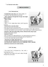
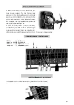
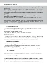
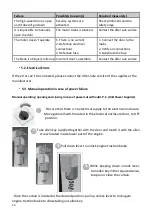

Inferior photocells adjustment
In order to correctly orientate photocells, you
have to use support for the fixing screw
available in the photocell support, vertically
leaning up to the light beam is reflected in the
mirror and sent back to the photocell. When
this happens, the 2 LED placed on photocell
electronic board will light on.
In order to verify that it operates correctly,
you have to pass the hand to cut the light
beam and the signal LED will be immediately
lighted and you could heard a small click from the contact change status.
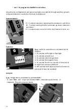
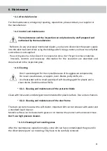
CONNECTION ON CONTROL BOX
RED
Cable
5(AC)
Terminal
BLACK
Cable
6(AC)
Terminal
GREEN
Cable
10(Photocell)
Terminal
YELLOW
Cable
9(Photocell)
Terminal
G
R
EE
N
YE
LL
O
W
B
LA
C
K
R
ED
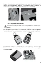
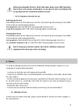
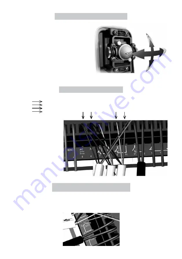
Additional external push button
Connection on 11 and 12 terminals. (Alternative push button)
19