

·
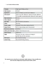
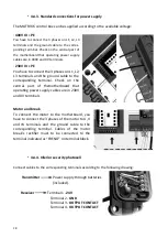
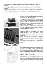
4.4.3. Standard connections for power supply
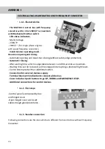
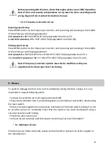
The MATRIX 6 control box can be supplied according to the available voltage:
· 400V III + PE
You have to connect the 3 phases on L1, L2, L3
terminals and the ground cable to the corres-
ponding terminal. Check on the central part of
the motherboard that operating power supply
cables are in 400V and 0V terminals.
· 230V III + PE
You have to connect the 3 phases on L1, L2,
L3 terminals and the ground cable to the
corresponding terminal. Check on the
central part of themotherboard that
operating power supply cables are in 230V
and 0V terminals
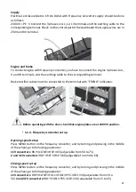
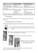
Motor and break
To connect the motor to the motherboard, you
have to connect the 3 phases of the motor to U, V
and W terminals and the ground cable to the
corresponding terminal. Cables of the motor
break’s rectifier must to be connected to the
terminal indicated as “FRENO” on terminal block.
·
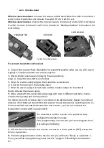
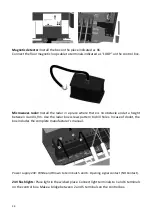
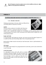
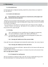
4.4.4. Inferior security photocell
Connect cables to the corresponding terminals according to the following drawing.
Transmitter
Power supply through batteries
(included).
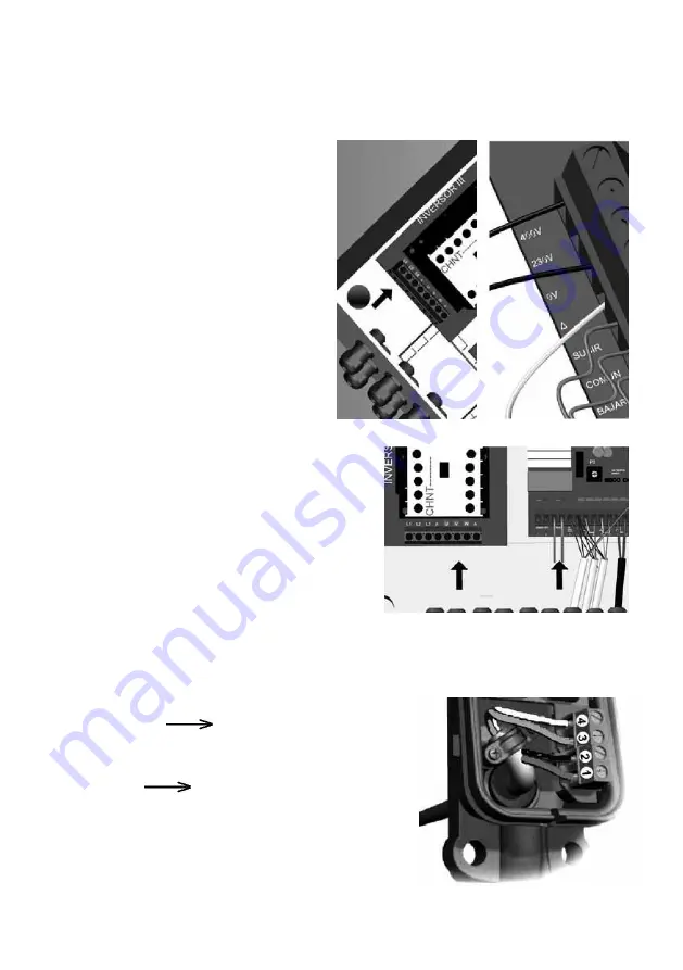
Receiver
Terminal 1 -
24V
Terminal 2 -
GND
Terminal 3 -
OUTPUT CONTACT
Terminal 4 -
OUTPUT CONTACT
18