background image


15 


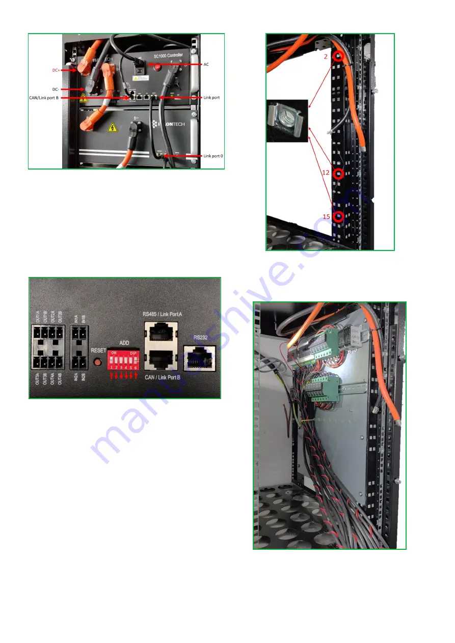
10. Connect DC cable type D to the DC + connector and DC cable 
type E to the DC- connector as shown above. 

11.  Connect  the  top  battery  module  and  the  Pylontech  control 

module with a communication cable as shown above 

12.  Connect  CAN  communication cable  ESO  -  control  module  in 

CAN / Link port B as shown above 

13. Make sure that the Pylontech control module is switched off 

and connect the AC cable as shown above. 


14. Check that the DIP switches on the control module are in the 

correct position as shown above. 


15. Install cage nuts for ESO distribution in holes no. 2, 12 and 15 

(counted from above) on the rows closest to the gables on the right 

side of the rack cabinet. 


16.  Attach  the  ESO  distribution  to  the  right  inside  of  the  rack 
cabinet as shown above. 

NOTE

 placement of terminal block for DC cable type D, DC cable 

type E and terminal block for DC cable to EnergyHub in the picture 

below (DC +, DC- and PE). 

Summary of Contents for Pylontech M1

Page 1: ...Installation manual Pylontech M1...

Page 2: ...LISH 11 6 Introduction 11 6 1 Included items 11 6 2 Cable list 11 6 3 Dimensions 11 6 4 Warnings and reservations 11 6 5 Explanation of safety notices 11 7 Installation 12 7 1 Placement 12 7 2 Prepara...

Page 3: ...H x B x D 2130 x 815 x 659 mm Vikt 1036 kg Pylontech batterimodul M tt H x B x D 150 5 x 330 x 628 mm Vikt 48 kg 1 4 Varningar och f rbeh ll UPPMANING Anv nd endast denna produkt enligt angivna instru...

Page 4: ...ch service rekommenderar vi att batteriet placeras med ett fritt utrymme framf r racksk pet p 1 m samt ca 40 cm p vardera sida om racksk pet 2 2 F rberedelser inf r installation 1 Avl gsna de tre vers...

Page 5: ...genom den v nstra ppningen 4 Koppla bort de f rmonterade adaptrarna fr n baksidan av alla ESO er enligt bilden ovan 2 3 Inkoppling av batterimoduler 1 Placera Pylontech SC100 Controller i facket l ng...

Page 6: ...tv nedersta batterimodulerna med kommunikationskabel enligt bilden ovan 7 Koppla samman vriga batterimoduler p h gra halvan av racksk pet med DC kablar typ A enligt bilden ovan 8 Koppla samman vriga...

Page 7: ...att Pylontech kontrollmodul r avslagen och anslut AC kabel enligt bilden ovan 14 Kontrollera att DIP switchar p kontrollmodulen st r i r tt l ge enligt bilden ovan 15 Montera korgmutter f r ESO distri...

Page 8: ...6 adaptrar Dessa 3 adaptrar ska anslutas till ESO nr 1 3 och 5 19 Anslut ESO 2 till en adapter utan Pre Charge kabel Koppla sedan samman ESO 1 och ESO 2 med en ethernetkabel enligt bilden ovan Eternet...

Page 9: ...f r ESO distribution i h l nr 3 11 13 25 och 37 enligt bilden ovan 23 Drag ut ESO erna cirka 5cm ur sk pet och montera sedan frontpl ten enligt bilden ovan 24 Placera ESO erna s att frontpl ten ligger...

Page 10: ...lerna laddas ur helt Detta r n got som litiumjoncellerna kan ta skada av 4 Urkoppling Vid urkoppling av ett Pylontech M1 se till att f ljande steg efterf ljs 1 St ng av liksp nningsn tet samt ppna bry...

Page 11: ...10...

Page 12: ...9 mm Weight 1036 kg Pylontech battery module Dimensions H x W x D 150 5 x 330 x 628 mm Weight 48 kg 6 4 Warnings and reservations RECOMMENDATION Only use this product according to the instructions sup...

Page 13: ...NOTE To facilitate installation and service we recommend that the battery is placed with a free space in front of the cabinet of 1 m and a free space of about 40 cm on each side of the rack cabinet 7...

Page 14: ...the left opening 4 Disconnect the pre assembled adapters from the back of all ESOs as shown above 7 3 Installation of battery modules 1 Place the Pylontech SC100 Controller in the compartment at the...

Page 15: ...battery modules at the bottom with a communication cable as shown above 7 Connect the battery modules on the right half of the cabinet with DC cables type A as shown above 8 Connect the battery modul...

Page 16: ...le is switched off and connect the AC cable as shown above 14 Check that the DIP switches on the control module are in the correct position as shown above 15 Install cage nuts for ESO distribution in...

Page 17: ...e 3 adapters must be connected to ESO no 1 3 and 5 19 Connect ESO 2 to an adapter without a Pre Charge cable Then connect ESO 1 and ESO 2 with an Ethernet cable as shown above The Ethernet cable is co...

Page 18: ...and the cover plate in holes no 3 11 13 25 and 37 as shown above 23 Pull the ESOs about 5 cm out of the cabinet and then mount the ESO front plate as shown above 24 Position the ESOs so that the front...

Page 19: ...arged This is something that lithium ion cells can damage 9 Disconnection When disconnecting a Pylontech M1 make sure that the following steps are followed 1 Switch off the mains supply and open the s...

Page 20: ...Electricity Reinvented...

Reviews: