FALCON II
23
5.04 Adjusting maximum output for central heating system
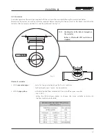
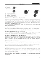
(fig. 22)
This adjustment must be carried out electronically using the “P3” adjustment screw starting with a cold central heating
system. Connect a pressure gauge to the pressure test point downstream of the gas valve. Rotate the temperature
adjustment screw to maximum then regulate the pressure to the value required, consulting the diagram (figs. 4 and 5).
Once this operation is complete, start up and shut down the burner two or three times using the thermostat. Check each
time that the pressure values remain as adjusted and that the burner ignites correctly. Otherwise
further adjustment is
necessary until the pressure remains stable on this value.
N.B.
- when carrying out this operation ensure that the boiler thermostat is set to maximum otherwise the
adjustment will not be accurate.
5.05 Adjusting central heating flow temperature
Central heating water temperature is adjusted by rotating the control knob (fig. 2 - part 63). Rotate the knob clockwise to
increase water temperature, anticlockwise to reduce water temperature. Temperature can be varied from a minimum of
30°C to a maximum of 85°C. However, we recommend not operating the boiler below 50°C.
5.06 Adjusting room temperature
(when a room thermostat is fitted)
Room temperature is controlled by positioning the room thermostat knob to the required value. The thermostat automatically
controls the boiler, temporarily interrupting the electrical supply subject to the room heat requirements.
5.07 Adjusting the central heating flow
t
by varying pump flow-head
T
he thermal head t (the difference in temperature between the delivery water and return water in the central
heating circuit) must be less than 20° c. This is obtained by varying pump flow rate and head using the multi-speed
variator (or switch) on the pump itself. Increasing the pump speed reduces t and vice versa. The minimum
differential must not be less than 11°C.
5.08 Adjusting central heating system pressure
The pressure of water in the central heating system, read on the control panel pressure gauge, is adjusted as
described in paragraph 3.07.
N.B. -
To avoid incurring unnecessary expense, in the event of boiler shut down, check that this is not caused by a lack of
electricity or gas, or low water pressure before calling the Customer Technical Service Helpline.
5.09 Gas conversion
The
following adjustment and conversion operations must be carried out by competent personnel. FER Limited
accepts no liability for damage to property or personal injury resulting from tampering with the boiler by
unauthorised persons. To convert the boiler from Nat Gas to LPG and vice versa, the main burner injectors must
be replaced. Minimum and maximum pressures must then be adjusted on the gas valve (see Adjustment page
22). JP02 must be moved to the LPG position.
Note: After converting the boiler from natural gas to liquid gas, fit the orange plate in the conversion kit
near the data plate.
Fig. 22
5.03 Adjustment
potentiometers
P1
=
C.H. temperature adjustment
P2
=
D.H.W. temperature adjustment
P3
=
C.H. output adjustment
P4
=
Ignition gas pressure adjustment
P5
=
Minimum gas pressure adjustment
+
-
+
-
P2
DHW
+
-
P3
+
-
P5
+
-
P4
P1
CH
Summary of Contents for FALCON II
Page 43: ......

