background image

PROGRAMMING SOFTWARE

To program the Feniex 4200 Controller, first visit  

feniex.com to download the software. 

Help

For assistance on how to use the software, please click 

the help button located on the top bar in the software 

interface.  You will find informative videos on how to 

program every function of the 4200 software system.

1)

 Connect the provided USB wire to the controller, and 

connect the other end of the USB port to the computer.

2)

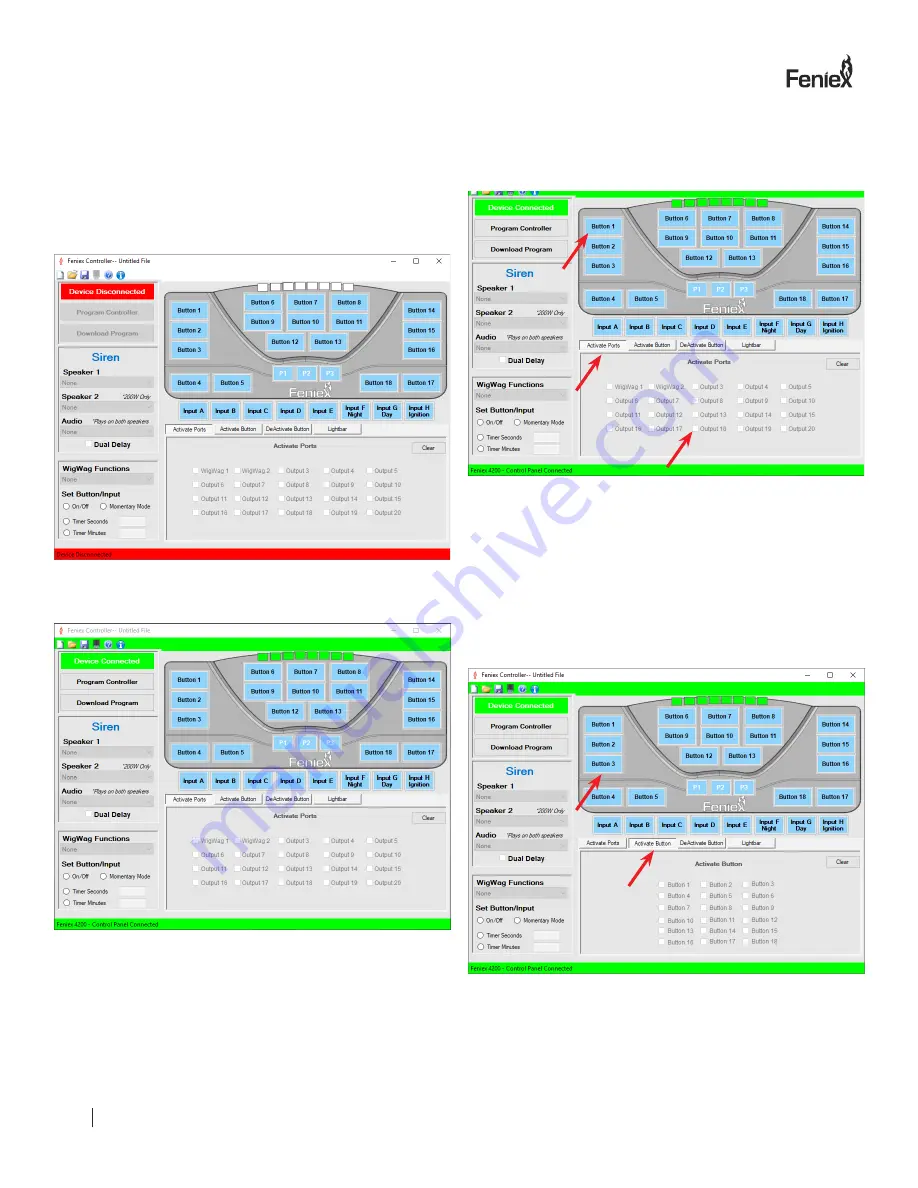
 When the controller is plugged in, the red box reading 

"Device Disconnected" will change from Red to Green will 

read: "Device connected." 

Ports 1-20 can be activated by: 

•  Button 

•  Input 

•  Slide Switch (p1, p2, p3)

3) Activate Ports 


Select button, input or slide switch and then check the box 

of the desired port. You can select as many ports as need-

ed with each button programmed. Each output is capable 

of 10 amps. For any product requiring more than 10 amps, 

use multiple ports to split the load. 

For example: For a spotlight that requires 15 amps, select 

the desired       button on the controller then use 2 ports to 

split the load. Don't exceed 30 amps per fuse quadrant. 

4) Activate Button

This


function programs the slide switch (p1, p2, p3) or 

inputs A-E to activate a       button. Please note a button 

cannot activate another button. Multiple buttons can be 

activated through the slide switch or input set up. 

TM

FENIEX //


INSTRUCTION MANUAL

WEB //


www.feniex.com

10

Summary of Contents for C-4200-DL

Page 1: ...y form distribute and make derivative works of the copyrighted material Accordingly any copyrighted material of Feniex and its licensors contained herein or in the Feniex products described in this Price List may not be copied reproduced distributed merged or modified transmitted transcribed stored in retrieval system or translated into any language or computer language in any form or by any means...

Page 2: ...Flash Patterns 4 System Specifications 4 Dimensions 4 Power Configuration 5 Power 5 Auto Power On 5 Wiring Diagram 5 Latching or Momentary Buttons 5 Alternating Wig Wag Flasher 5 Wig Wag Functions 5 Mounting Instructions 6 Swivel Mount Installation 6 L Bracket Installation 6 Button Legend Sheet 7 TABLE OF CONTENTS TM FENIEX INSTRUCTION MANUAL WEB www feniex com 2 ...

Page 3: ...eniex Industries Inc will not be held responsible for any costs associated with equipment removal and or re installation resulting from a warranty claim It is the sole responsibility of the party initiating a warranty claim to pay shipping charges associated with returning a product to Feniex Industries for repair or replacement SERVICE AFTER EXPIRATION Feniex Industries will still provide service...

Page 4: ...uilt in Switch Type Latching Momentary Timed Buttons Rubberized Backlit 2 Colors Button Legends 4 Sheets Relay Dimensions 6 3 W x 3 3 H x 4 4 D Keypad Dimensions 6 9 W x 4 6 H x 1 0 D Bluetooth Dimensions 3 2 W x 1 5 H x 0 9 D Bluetooth Range 35 40ft Warranty 2 Years WIG WAG FLASH PATTERNS Single Flash Slow Quad Flash Slow Single Flash Fast Quad Flash Fast Single Flash Combo Quad Flash Combo Tripl...

Page 5: ... Terminal PIN FUNCTION POLARITY 11 Programmable Output 11 12v 12 Programmable Output 12 12v 13 Programmable Output 13 12v 14 Programmable Output 14 12v 15 Programmable Output 15 12v 16 Programmable Output 16 12v 17 Programmable Output 17 12v 18 Programmable Output 18 12v 19 Programmable Output 19 12v 20 Programmable Output 20 12v PIN FUNCTION POLARITY A Programmable Input 12v B Programmable Input ...

Page 6: ... components could be damaged by the drilling process 5 Drill two mounting holes on the mounting surface making sure no vital components of the surface are damaged 6 Using customer supplied screws secure the 4200 Mini to the mounting surface 6 Place the unit against the intended mounting surface 7 Mark the areas where the mounting holes will be drilled If the mounting surface is part of the vehicle...

Page 7: ...12 12 13 13 14 14 15 15 16 16 17 17 18 18 19 P1 20 P2 P3 Input Polarity A F Night B G Day C H Ignition D E Use this page to record the products connected to each outlet to assist when programming the control head with the provided software package TM FENIEX INSTRUCTION MANUAL WEB www feniex com 7 ...

Page 8: ...ositive Programmable Input Negative Programmable Input H G F E D C B A Input Examples Highbeam Override Park Kill Reverse Override The ignition input must be activated before the system can be used to control attached equipment Tip Once the appropriate ignition input is connected install a small jumper wire between inputs H G to activate keypad backlight in Day Mode TM FENIEX INSTRUCTION MANUAL WE...

Page 9: ...ghbeam Body Control Module 1 2 3 4 5 6 7 8 9 10 11 12 13 14 15 16 17 18 19 20 H G F E D C B A Highbeam Override Using the programming software configure Input E in this example to Highbeam Override see page 17 TM FENIEX INSTRUCTION MANUAL WEB www feniex com 9 ...

Page 10: ...an be activated by Button Input Slide Switch p1 p2 p3 3 Activate Ports Select button input or slide switch and then check the box of the desired port You can select as many ports as need ed with each button programmed Each output is capable of 10 amps For any product requiring more than 10 amps use multiple ports to split the load For example For a spotlight that requires 15 amps select the desire...

Page 11: ... on 1 switch 7 Timer The timer function allows any button to continue function ing for a set period of time after it s been disabled Timer can be set for any duration between 1 second to 1 hour This applies for all inputs A H and all buttons The slide switch cannot be programmed for timer or momentary functions The momentary function only applies to buttons and allows a button to activate only whe...

Page 12: ...Storm siren is installed the audio tones will always play on both speakers For example Tone 1 programmed on speaker 1 will play through both speakers 1 and 2 on a 200W siren 10 Dual Delay This function works when a 200W Storm siren is connect ed to the 4200 Dual delay is a check box at the bottom of the siren section When using a 200W siren and have one switch activating the same siren tone dual d...

Page 13: ...nction of the lightbar select a desired switch input slide switch button then select the lightbar function Multiple functions can be selected on 1 switch Program the appropriate input highbeam signal to over ride the flashing wig wag function with a stead on signal TM FENIEX INSTRUCTION MANUAL WEB www feniex com 13 ...

Page 14: ...http www feniex com s 4200 The app is not yet available on Google Play 4 Turn Bluetooth on using handheld device 5 Press and hold pairing switch button on Feniex Bluetooth device for 3 seconds 6 In the 4200 app select connect in the upper right corner 7 Select Search for device for Android or Scan for Apple 8 Enter password For android devices select Feniex 4200 and enter password 1111 For apple d...

Page 15: ...used for low beams Make sure to wire each output to the positive side of the high beam or low beam Be sure to completely cut the wire to not splice into it to percent feedback 7 How do I wire the highbeam function from the vehicle Run the switch side wire after its cut off from the high beam bulb into the 4200 s input C D or E In the programming software select the input of the vehicle s highbeam ...

Reviews: