background image

Feniex Industries, Inc.
1.800.615.8350
 /


feniex.com

8

1. Remove the top of the lightbar by removing the 8 screws          

on the top cover.

2. 

Pull the top plastic lens off.

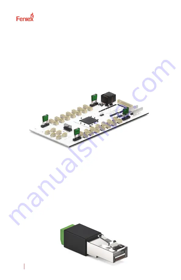
3. Add  one  of  the  three  supplied  jumpers  to  position  one  as                      

shown in the image below. The remianig jumpers are includ-

ed in case one is lost. Only one is needed for this.

4. Place the cover back on and secure with hardware that 

was removed in step one.

5. Connect the white and green wires into the screw termi-

nals of the RS-45 into the screw terminal adapter included 

with the 4200.

6. Plug in the RJ-45 adapter to any one of the Data Link 

outputs on the 4200 Relay. See the image below for wiring 

to adapter.

RJ-45 Terminal Adapter to Green/White Wires from Fusion-

S Product Wiring:

A: White

B: Green

FUSION-S 49" AND 60" LIGHT 

BARS AND DATA LINK

Summary of Contents for 4200-DL

Page 1: ...ghted material Accordingly any copyrighted material of Feniex and its licensors contained herein or in the Feniex products described in this Price List may not be copied reproduced distributed merged...

Page 2: ...provides all the information necessary to safely operate the previously listed products of Feniex Industries Inc Please read this manual thoroughly before installing or operating your new product in...

Page 3: ...NT DIMENSIONS 6 9 4 6 1 0 4 4 6 3 3 3 1 4200 Data Link Relay 1 1 2 4200 Controller U Shaped Bracket Ethernet Cable COMPONENTS 1 USB Cable 2 4 Screws Button Legends 4200 Controller 4200 Data Link Relay...

Page 4: ...Standby Current 60 Amps 60 Amps 100mA External Fuse 125 of Circuit Load Programmable Inputs System Inputs Relays 2 Ground 3 Positive Ignition Day Night Solid State Built in Switch Type Latching Moment...

Page 5: ...on the size of screw choice Important Make sure not to dam age any vital parts of the vehicle or mounting surface Do not mount anywhere that interferes with the vehicle air bag 2 Re attach the contro...

Page 6: ...e products connected to each outlet to assist when programming the control head with the provided software package Outputs Buttons 1 18 P1 P3 1 1 2 2 3 3 4 4 5 5 6 6 7 7 8 8 9 9 10 10 11 11 12 12 13 1...

Page 7: ...tputs of the 4200 Relay 2 Pull the top plastic lens off 3 Add one of the three supplied jumpers to position one as shown in the image below The remainig jumpers are includ ed in case one is lost Only...

Page 8: ...Only one is needed for this 4 Place the cover back on and secure with hardware that was removed in step one 5 Connect the white and green wires into the screw termi nals of the RS 45 into the screw t...

Page 9: ...rt to the computer 2 When the controller is plugged in the red box reading Device Disconnected will change from Red to Green will read Device connected Ports 1 20 can be activated by Button Input Slid...

Page 10: ...utton 6 right arrow button 8 center out button 7 When activating button 6 deactivate button 7 and 8 6 Lightbar This function works when you have a full size lightbar connected To activate a function o...

Page 11: ...ed switch input slide or button then select the tone from the drop down menu If using a 100W siren only select speaker 1 For 200W sirens make sure to highlight speaker 1 and speaker 2 9 Audio under si...

Page 12: ...This function works when a 200W Storm siren is connected to the 4200 Dual delay is a check box at the bottom of the siren section When using a 200W siren and have one switch activating the same siren...

Page 13: ...to edit labels on buttons FREQUENTLY ASKED QUESTIONS 1 How do I know if there is power to my 4200 Relay A flashing green LED light on the PCBA will indicate if there is power to the board if the firmw...

Reviews: