


FEMA ELECTRÓNICA . Series S . S40-P
5
The instrument has two menus accessible to the user :
‘Configuration menu
’ (key SQ) (
<
)
‘
Fast access
’ menu (key UP) (
5
)
Configuration menu
The ‘
configuration menu
’ modifies the configuration parameters to
adapt the instrument to the application needs. To access the ‘
con
-
figuration menu
’ press for 1 second the SQ (
<
) key. This access can
be blocked by activating the ‘
Password
’ (‘
PASS
’) function. While
operating the ‘
configuration menu
’, the alarm status is ‘hold’ to the
status they had before accessing the menu, and the output and con
-
trol modules remain in ‘
error
’ state. When leaving the ‘
configuration
menu
’, the instrument applies a system reset, followed by a brief
disconnection of the alarms and the output and control modules.
Functionality is then recovered.
For a detailed explanation on the ‘
configuration menu
’ see section
, and for a full view of the ‘
configuration menu
’ structure see
1.11.
‘
Fast access
’ menu
The ‘
fast access
’ menu is an operator configurable menu, providing
fast and direct access to the most usual functions of the instrument
with a single key pad stroke. Press key UP (
5
) to access this menu.
See section
for a list of functions eligible for ‘
fast access
’ in
this instrument. The ‘
Password
’ (‘
PASS
’) function does not block ac
-
cess to this menu. Accessing and modifying parameters in the ‘
fast
access
’ menu does not interfere with the normal functionality of the
instrument, and it does not generate any system reset when validat
-
ing the changes.
Front key pad description
Key SQ
(
<
) - press the SQ (
<
) key for 1 second to access the ‘
con
-
figuration menu
’. Inside the menu, the SQ (
<
) key functions as a
‘ENTER’ key. It selects and accesses the menu option currently dis
-
played. At menus with numerical value entries, it validates the num
-
ber displayed.
Key UP
(
5
) - the UP (
5
) key gives access to the ‘fast access’ menu.
Inside the menus, it moves vertically through the different menu op
-
tions. At menus with numerical value entries, it modifies the digit
selected by increasing its value to 0, 1, 2, 3, 4, 5, 6, 7, 8, 9.
Key LE
(
3
) - inside the menus, the LE (
3
) key functions as the ‘
ES
-
CAPE
’ key. It leaves the selected menu, and eventually, will leave the
whole menu. When leaving the ‘
configuration menu
’ with the LE (
3
)
key, the changed parameters are activated. At menus with numeri
-
cal value entries, the LE (
3
) key allows to select the active digit. To
modify the value of the selected digit use the UP (
5
) key.
Menu ‘rollback’
After 30 seconds without interaction from the operator, the instru
-
ment will rollback and leave the ‘
configuration menu
’ or the ‘
fast ac
-
cess
’ menu. All changes will be discarded.
1.8 How to operate the menus
Messages and errors
‘h.udr’
‘h.oVr’
Hardware underrange (‘
h.udr
’) / overrange (‘
h.ovr
’). In
-
put signal is lower / higher than the minimum / maxi
-
mum signal the instrument can detect.
‘d.udr’
‘d.oVr’
display underrange (‘
d.udr
’) / overrange (‘
d.ovr
’). The
instrument already displays the minimum / maximum
value possible (-1999 / 9999).
‘hoLd’
the ‘
hold
’ function is active. Display is on hold.
‘P.hLd’
the ‘
Peak&Hold
’ function is active.
‘Err.0’*
at the ‘
scaling
’ (‘
ScAL
’) menu entry, the defined slope is
higher than ‘5000’ (slope almost vertical). Entered values
are dismissed and default values are activated.
‘Err.1’
incorrect password.
‘Err.2’
at ‘
oPt.X
’ menu entry. Installed module is not recognized.
‘Err.3’
at ‘
segment linearization
’ (‘
SLin
’) menu entry. The ‘input
X’ values entered are not in growing succession.
‘Err.5’*
at ‘
segment linearization
’ (‘
SLin
’) menu entry. the de
-
fined slope is higher than ‘5000’ (slope almost vertical).
Entered values are dismissed and default values are ac
-
tivated
‘Err.8’
excitation voltage overload.
Table 3 - Messages and error codes
The error messages are shown on display in flash mode.
(dhI-dLo) [counts]
(IhI-ILo) [mA or Vdc]< 5000
*slope calculation for errors ‘
Err.0
’ y ‘
Err.5
’.
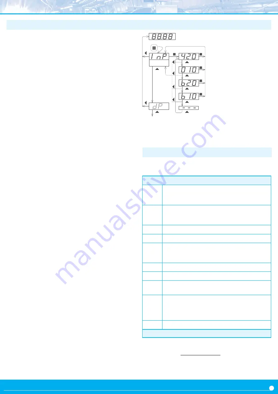
Input
Example of operation inside the
‘configuration menu’.
1. The SQ (
<
) key enters into the
‘configuration menu’.
2. The SQ (
<
) key enters into the
‘
InP
’ option menu.
3. The UP (
5
) key moves through
the menu options.
4. The SQ (
<
) key selects the
desired range and returns to the
‘
InP
’ menu.
5. The LE (
3
) key leaves the ac
-
tual menu level and moves to the
previous menu level.
6. The LE (
3
) key leaves the ‘con
-
figuration menu’. Changes are ap
-
plied and saved at this moment.
(2)
(3)
(3)
(3)
(3)
(3)
(4)
(4)
(4)
(4)
(5)
(5)
(5)
(5)
(3)
(3)
(6)
(6)
(1)
1.9 Messages and errors
Summary of Contents for S40-P
Page 20: ......


