www.felixprinters.com
Page
33
of
65
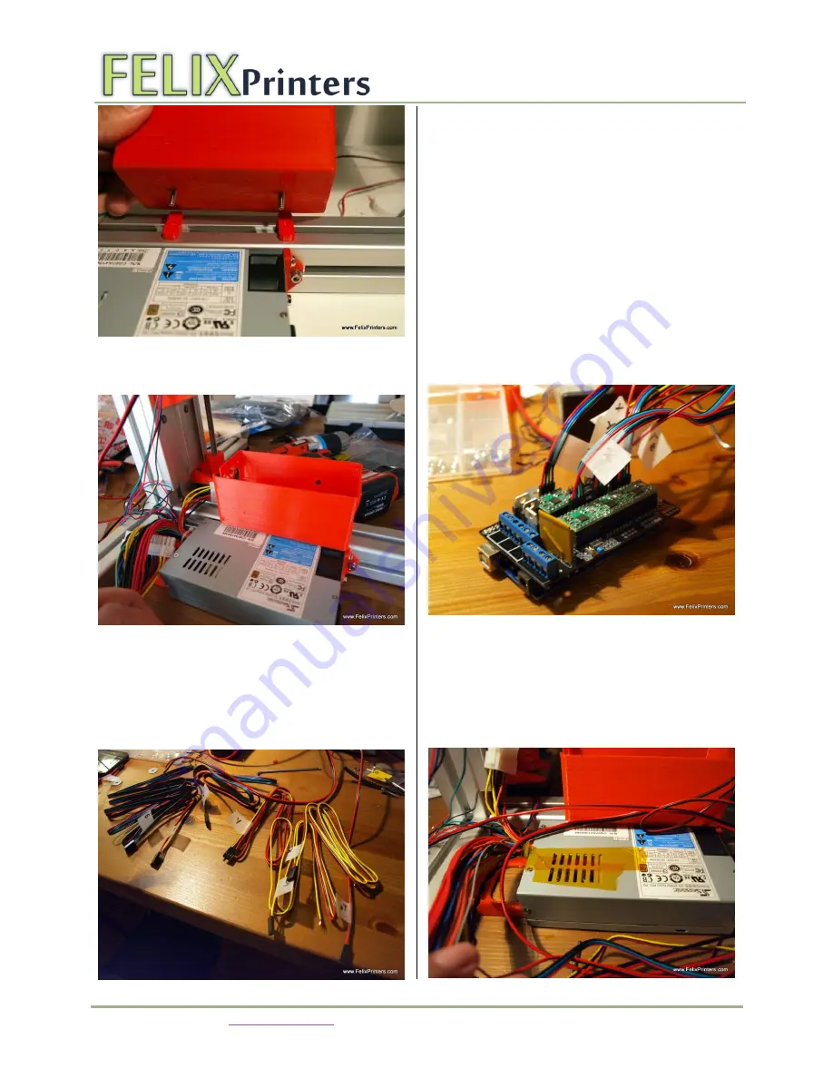
Mount the case also with t-slot nuts and the ramps_support parts.
Use the m4x12 buttonhead screws.
IMPORTANT
: Align the front face of the ramps case with the front
face of the powersupply. When the electronics case is placed too
close to the vertical beam, the z-axis carrier will touch the ramps
case, before it is at the end of its stroke.
Put labels on all cables
It is very usefull to label all the cables, especially when you want
remove a cable in the future for whatever reason. A easy way of
labeling is to fold a piece of tape around near the connectors, and
write something on it with a permanent marker.
The three wired cables are for the opto sensors, the 4 wired cables
are for the motors and the 2 wired cables are for the heated bed
and hot-end temperature sensors (these are already mounted onto
the parts.).
10.2
Connect all possible wires to the electronics
board.
We want to work our way from the electronics board to the components.
Connect all the pre-crimped cables, onto the board, the labels should
correspond to the position on the board. Try to group the 3wire cable
together.
Tip: make good use of the cable ties supplied with the kit. They are great
to form nice cable loops. Afterwards, it is easy to remove the unnecessary
ones.


