Extension tables
Using the exploded assembly diagrams supplied with the machine, determine the
correct screws to use for the extension table(s). Begin as shown in the picture below
wi
t
h the support members. Note: Machines with
48" (
1250mm
)
rip capacity also
have an
additional support member not shown in the pictures below, but in later steps.
(picture shows full length
31" (
800mm
)
Rip capacity)
Continued…
11.Assembly
Summary of Contents for Hammer
Page 1: ...Machine Setup Guide InstallVersion1 09...
Page 5: ...15 Completion You re Good To Go 16 FAQ s 17 Links Contact Details Contents 3...
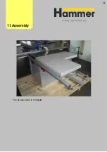
Page 32: ...The rip fence side is complete 11 Assembly...
Page 74: ...Figure SS03 2 End position 2 Adjustments Alignme nt Link SS03 continued...
Page 79: ...Figure SS07 3 Crosscut stop and block adjustment Adjustments Alignme nt Link SS07 continued...


