Felder FB 540 User Manual Download Page 45

45

Eigentum der Firma Felder KG. Es darf 

ohne Erlaubnis weder veräußert, kopiert 

noch 3. Personen mitgeteilt werden.

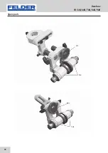
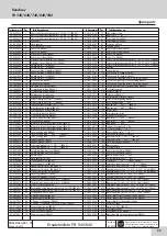
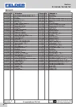
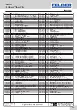
Ersatzteilliste FB 540/640

gültig ab

05/2010

FB540/640-E01_01

Stand 10/2010

Pos.

Pos.

teilenummer

teilenummer

teilebezeichnung

teilebezeichnung

AC-5020033 

oberes Speichenschwungrad (incl. 2;3;4;6;17) (FB640) 

AC-5020105 

oberes Scheibenschwungrad (incl. 2;3;4;6;17) (FB540) 

AC-5020121 

oberes Scheibenschwungrad (incl. 2;3;4;6;17) (FB640) 

AC-3205046 

Kugellager 

AC-5210036 

Abstandhalter 

AC-3072039 

Schließring D=62 (hole) 

AC-5150029 

obere Türe (FB540) 

AC-5150033 

obere Türe (FB640) 

AC-5050069 

Achse oberes Rad (FB540) 

AC-5050071 

Achse oberes Rad (FB640) 

AC-5030010 

11 

Gleitlager oberes Rad (incl. 20) (FB540) 

AC-5030014 

11 

Gleitlager oberes Rad (incl. 20) (FB640) 

AC-3262009 

12 

Axiallager (incl. 14) (FB540) 

AC-3262010 

12 

Axiallager (incl. 14) (FB640) 

AC-5120035 

13 

Spannungsblatt - Stahlplatte (FB540) 

AC-5120037 

13 

Spannungsblatt - Stahlplatte (FB640) 

AC-3261009 

14 

Axiallager (incl. 12) (FB540) 

AC-3261010 

14 

Axiallager (incl. 12) (FB640) 

AC-3402083 

15 

Schwenkhebel (FB640) 

AC-3402084 

15 

Schwenkhebel (FB540) 

AC-3401501 

16 

Anschlag für Neigungswinkel

AC-3458002 

17 

Gummibezug für Rad (FB540) 

AC-3458003 

17 

Gummibezug für Rad (FB640) 

AC-3177002 

18 

Drahtanzeige für Spannung 

AC-3178103 

18 

Drahtanzeige für Spannung 

AC-5030011 

20 

Support sliding part (incl. 11) (FB540) 

AC-5030016 

20 

Support sliding part (incl. 11) (FB640) 

AC-5120034 

21 

Spannungskabelanschlag (incl. 11;20)

AC-3071020 

22 

Schließring D=25 (shaft) (FB540) 

AC-3071024 

22 

Schließring D=30 (shaft) (FB640) 

AC-5051102 

23 

Gestell für Blattschutz (FB540) 

AC-5051104 

23 

Gestell für Blattschutz (FB640) 

AC-3402080 

24 

Griff für Anschlusswinkel (FB540) 

AC-3402081 

24 

Schwenkhebel (FB640) 

AC-5120401 

25 

Blattschutz - Blatt Führungslagersystem (FB540) 

AC-5120402 

25 

Blattschutz - Blatt Führungslagersystem (FB640) 

AC-5120054 

26 

Blattschutz - Blatt Führungslagersystem (FB640) 

AC-5070005 

32 

Trunnion tilting table (FB540) 

AC-5070009 

32 

Trunnion tilting table *** EXP *** (FB640) 

AC-5070010 

32 

Trunnion tilting table *** CE *** (FB640) 

AC-5080010 

34 

Spannschraube (FB540) 

AC-5080011 

34 

Spannschraube (FB640) 

AC-5270003 

35 

Feder Stahlblattschutz *** CE *** (FB540) 

AC-5270004 

35 

Feder Stahlblattschutz *** CE *** (FB640) 

AC-5031001 

36 

Parallelanschlag (cast iron) (FB540) 

AC-5031002 

36 

Parallelanschlag (cast iron) (FB640) 

AC-5051250 

37 

Spezialmutter

AC-5060011 

38 

Abstandhalter (incl. 48) 

AC-3104085 

39 

schwenkbarer Stop (FB640) 

AC-5400606 

39 

schwenkbarer Stop (FB540) 

AC-3410640 

42 

Handkurbel für oberes Rad (FB540)

AC-3410641 

42 

Handkurbel für oberes Rad (FB640)

AC-3401270 

43 

Oberer und unterer Türschließgriff 

AC-5140001 

45 

Spannungsblattfeder (FB540) 

AC-5140002 

45 

Spannungsblattfeder (FB640) 

AC-5400013 

46 

Tension blade indication box (incl. 18) (FB540) 

AC-5400015 

46 

Tension blade indication box (incl. 18) (FB640) 

AC-5030044 

47 

Support of Parallelanschlag 

AC-5400506 

48 

Rundstahlanschlagstützungsupport fence (incl. 38) (FB540) 

AC-5400507 

48 

Rundstahlanschlagstützungsupport fence (incl. 38) (FB640) 

AC-3407257 

56 

Locking handle fence support 

AC-5400600 

59 

V-Riemenspannung (FB640) 

AC-5400602 

59 

V-Riemenspannung (FB540) 

AC-3417010 

60 

V-Riemen, für Aggregat (FB540) 

AC-3417011 

60 

V-Riemen, für Aggregat (2pcs for machines) (FB640) 

AC-5110002 

61 

Motorriemenscheibe (FB540) 

AC-5110042 

61 

Motorriemenscheibe (FB640) 

AC-5070007 

70 

Trunnion support (FB540) 

AC-5070011 

70 

Trunnion support (FB640) 

AC-3104112 

73 

schwenkbarer Stop 

AC-5140006 

80 

Bremsfeder *** EXP *** 

AC-5150031 

81 

Türverbindung (FB540) 

AC-5150035 

81 

Türverbindung (FB640) 

AC-3028381 

83 

Schraube M12x60 

AC-5210003 

87 

Zahnrad flange 

AC-5050070 

88 

Achse unteres Rad (FB540) 

AC-5050072 

88 

Achse unteres Rad (FB640) 

AC-5150030 

89 

untere Türe (FB540) 

AC-5150034 

89 

untere Türe (FB640) 

AC-5020037 

95 

unteres Speichenschwungrad (incl. 91;92;93;94;132) (FB640) 

AC-5020109 

95 

unteres Scheibenschwungrad (incl. 91;92;93;94;132) (FB540) 

AC-5020125 

95 

unteres Scheibenschwungrad (incl. 91;92;93;94;132) (FB640) 

AC-5190001 

98 

Zahnrad 

AC-3086114 

99 

Spannscheibe 

AC-3410741 

100  Post rise and fall handle (FB540) 

AC-3410746 

100  Post rise and fall handle (FB640) 

AC-5010022 

107  Tisch ohne Aussparung für den Anschlag (FB540) 

AC-5010023 

107  Tisch mit Aussparung für den Anschlag (FB540) 

AC-5010032 

107  Tisch ohne Aussparung für den Anschlag (FB640) 

AC-5010033 

107  Tisch mit Aussparung für den Anschlag (FB640) 

AC-5210005 

109  Tischplatteneinsatz

AC-3041061 

110  Schraube M6x16 

AC-1030711 

111  Zuführrinne (FB640) 

AC-5210101 

112  Holzeinsatz Zuführrinne (FB640) 

AC-5210009 

114  vorderer Absaugabzug (FB640) 

AC-5210007 

126  Kunststoffabdeckung *** EXP ***

AC-5120015 

127  Bremsbelag *** EXP *** (FB540) 

AC-5120016 

127  Bremsbelag *** EXP *** (FB640) 

AC-5210004 

134  Bürstenträger

AC-5210100 

135  untere Bürstenscheibe

AC-5210008 

145  Polykarbonat Blattschutz 

AC-5150201 

147  Bremshebel *** EXP *** (FB540) 

AC-5150202 

147  Bremshebel *** EXP *** (FB640) 

AC-5180001 

148  Bremspedal *** EXP *** 

AC-5210011 

150  seitlicher Dunstabzug D=120 

AC-4505010 

151  Tür Microschalter *** CE *** 

AC-5120022 

152  Microschalterschutz *** CE *** 

AC-3162052 

155  Gelenk mit fixierender Schraubes 

AC-5125020 

160  Untertischschutz *** EXP *** (FB540) 

AC-5125030 

160  Untertischschutz *** EXP *** (FB640) 

AC-3441001 

165  Holz - Abschiebevorrichtung *** CE *** 

AC-5700031 

166  Erdungskabel 

AC-1030382 

184  justierbare Platte 

AC-1030321 

189  nicht rotierende Platte (FB540) 

AC-1030344 

189  nicht rotierende Platte (FB640) 

AC-4505001 

191  Bremse Microschalter *** EXP ***

AC-5120030 

192   Microschalter Bremse *** EXP ***

AC-5120075 

193  Schalterbox *** CE *** (FB540, FB640) 

AC-5120133 

194  Safety box trunnion group *** CE *** (FB540) 

AC-5120134 

194  Safety box trunnion group *** CE *** (FB640) 

AC-5400107 

200  Sägeblattspanner (incl. 11;12;13;14;20;21;34;45) (FB540) 

AC-5400108 

200  Sägeblattspanner (incl. 11;12;13;14;20;21;34;45) (FB640) 

AC-5400201 

201  Zahnradsystem (incl. 87;98;99;100) (FB540) 

AC-5400203 

201  Zahnradsystem (incl. 87;98;99;100) (FB640) 

AC-5400053 

202  Bremssystem (incl. 80;126;127;147;148) (FB540) 

AC-5400055 

202  Bremssystem (incl. 80;126;127;147;148) (FB640) 

AC-5400557 

203  Parallelanschlagsystem (incl. 36;37;38;47;48;56) (FB540) 

AC-5400558 

203  Parallelanschlagsystem (incl. 36;37;38;47;48;56) (FB640) 

AC-5400760 

204  Blattschutzsystem (incl. 25;26A;35;110;145) (FB540) 

AC-5400761 

204  Blattschutzsystem (incl. 25;26;35;110;145) (FB640) 

AC-3723002 

210  oberes Blatt für Führungslager GL456 (FB540) 

AC-3723004 

210  oberes Blatt für Führungslager GL789 (FB640) 

AC-3723003 

211  unteres Blatt für Führungslager GL456

AC-3723101 

213  Einwalze GL456 

AC-3723102 

213  Einwalze GL789 (FB640) 

AC-3723104 

214  Seitenlager GL456 

AC-3723105 

214  Seitenlager GL789 (FB640)

AC-5250020 

26A  Blattschutz - Blatt Führungslagersystem (FB540)

Bandsaw
FB 540/640/740/840/940

Spare parts

Summary of Contents for FB 540

Page 1: ...Keep this manual handy and in good condition for continual reference Dok ID 013 1 4002 Englisch 2017 06 09 User Manual Bandsaw FB 540 640 740 840 940 translation...

Page 2: ...n the vicinity of the machine so that it is accessible to operators when using maintaining or repairing the machine Attention The machine must be inspected immediately upon arrival If the machine has...

Page 3: ...ork safety 9 2 7 Personal safety 10 2 8 Hazards arising from the machine 10 2 9 Other risks 10 3 Declaration of Conformity 11 4 Specifications 12 4 1 Dimensions and weight 12 4 2 Operation and storage...

Page 4: ...Table pad and wooden pad for dust extraction 28 7 4 5 Direction of cut and parallelism 28 7 4 6 Tilting the table 29 7 5 Brake system 29 7 5 1 Brake system maintenance and adjustment 29 7 5 2 Replaci...

Page 5: ...5 Bandsaw FB 540 640 740 840 940 Table of Contents...

Page 6: ...persons who work on or with the machine All descriptions texts drawings photos and other depictions are protected by copyright and other commercial laws Illegal use of the materials is punish able by...

Page 7: ...sposal laws must always be complied with General To order spare parts the following information is required Serial number and Model Year of manufacture Spare part number according to the following exp...

Page 8: ...erly or em ployed for purposes other than those it was designed for The chapter entitled Safety offers an overview of all the important safety considerations necessary to optimise safety and ensure th...

Page 9: ...st be briefed about all functions and potential dangers of the machine Spe cialist staff is a term that refers to those who due to their professional training know how experience and knowledge of rele...

Page 10: ...the results of this analysis and correspond to state of the art technology The machine is considered operationally safe when used properly Nevertheless there are some residual risks that must be consi...

Page 11: ...eclaration of Conformity according to Machine Guidelines 2006 42 EG We hereby declare that the machine indicated below which corresponds to the design and construction of the model we placed on the ma...

Page 12: ...rges Attention All operations may only be executed by an authorised electrical technician Specifications FB 540 FB 640 FB 740 FB 840 FB 940 Wheel diameter mm 540 640 740 840 940 Wheel speed rpm 950 81...

Page 13: ...es with the R S T clamps L1 L2 L3 and the yellow green electrical conductor with the earth ing clamp Pe When the machine is first switched on check the rota tional direction and if incorrect exchange...

Page 14: ...sed to 25 28 m s to ex tract dust from more humid materials over 12 Only flame resistant vacuum hoses can be used conform ing to DIN 4102 B1 and any other safety regulations in effect See the FELDER c...

Page 15: ...ht adjustment BRBlade tension hand wheel BSMitre fence BTSaw blade tension indicator window BUOn Off switch CLWheel door look CMVacuum connector CNTable tilt clamping lever COTable tilt Fig 3 Overview...

Page 16: ...KW HZ PH V NR TYPE XXXXXXXX XXX XXX XX XX 400 3 50 7 5 15 20xx Bandsaw FB 540 640 740 840 940 Setting up the machine 5 2 Data plate The data plate displays the following specifications Manufacturer in...

Page 17: ...Attention Risk of material damage Only operate the machine in ambient temperatures from 10 to 40 C If the instructions are not followed damage may occur during storage Ensure that there is sufficient...

Page 18: ...uipment such as roll supports and additional tables There are 4 threaded holes located in the base plate of the machine where the levelling screws supplied with the machine can be screwed into 6 2 1 S...

Page 19: ...rrow workpieces close at hand Before switching on the machine always check to make sure that there are no other persons in the immediate vicinity of the machine During operation When changing to anoth...

Page 20: ...The white indicator light on the control panel signals that electrical power is present Push in the motor safety switch push button Fig 7 Push button Fig 8 Drive motor Operation Push button Motor saf...

Page 21: ...rive motor turn the star delta switch onto the Y setting and hold it there until the machine has reached its full speed switch to the next setting The av erage run up time is approx 4 8 seconds To swi...

Page 22: ...ick as depicted in Fig 13 to prevent your hands from coming too close to the saw blade Fig 12 Push stick 7 3 2 Cutting round workpieces in the transverse direction 7 3 3 Longitudinal cut of narrow or...

Page 23: ...pment as depicted in the figure Fig 14 Angular cuts Use auxiliary equipment as depicted in the figure Fig 15 Circular cuts Use auxiliary equipment as depicted in the figure Fig 16 Cross cut 7 3 6 Circ...

Page 24: ...ay If the gap is too small the blade will overheat and rupture 7 4 1 Blade selection and maintenance Do not use kinked ruptured or bent saw blades For soft wood the set should be a max of twice the th...

Page 25: ...trude over the wheel edges Fig 18 Work table 7 4 2 Assembling and adjusting the saw belt To be able to mount the saw belt it is necessary to air the motor brake as it will otherwise prevent the wheels...

Page 26: ...ards A quarter of a turn is sufficient to change the movement distinctly Once the setting is cor rect clamp the clamping lever again tightly Close the saw belt duct and both doors and position the air...

Page 27: ...ing The guide rollers should be positioned approx 2 mm behind the saw belt teeth The rear support roller prevents strong pushing back of the saw blade during the cut and should be clamped 1 2 mm behin...

Page 28: ...wheel diameter have a second dust extraction port located at the front of the machine below the working table To maintain the extraction ca pacity change the wooden pad if the cutting gap is get ting...

Page 29: ...ped with an electromechanical brake which guarantees that all the moveable parts will come to a stop within 10 seconds once the machine has been switched off The brake shoes of the brake will wear out...

Page 30: ...ropeller moves away from the moveable rotor and the maximum air gap is achieved Reset the air gap to its original value with this screw once the brake ring has been replaced COIsk screws CPThrust coll...

Page 31: ...lean Components and tools that are not put in their correct place or put away may be the cause of accidents Install the safety equipment according to the instruc tions and check that it functions prop...

Page 32: ...s are pre adjusted and may not be adjusted 8 2 1 Replacing the V belt Loosen the belt tension as instructed above Remove the screw and loosen the 2 indicated screws Pull out the wheel with the shaft R...

Page 33: ...m the wheel surfaces The wheel bearings are sealed and do not need to be lubricated again It is not necessary to grease any parts on the machine as the circulating saw dust would otherwise immedi atel...

Page 34: ...elops Strictly speaking In the event of a breakdown which creates danger for either personnel or equipment the machine should be stopped immediately by activating the emergency stop Also disconnect th...

Page 35: ...meter of the wheel Defect or soiled wheel running surfaces Incorrectly aligned wheels Felder The saw blade is rupturing on the rear side Feed rate or pressure is too high during cutting Poor welded jo...

Page 36: ...r light HL2 10 white Indicator light SQ Fail safe transmitter YB1 Magnetic brake FU1 2 Fuse 1 A Key Circuit diagram FB 740 840 940 QS1 Main switch QF2 Motor safety switch QS3 Star delta switch KA Unde...

Page 37: ...37 Bandsaw FB 540 640 740 840 940 Fig 28 Circuit diagram FB 450 540 640 3P N 10 1 Bandsaw FB 540 640 3P N Electrical circuit diagram...

Page 38: ...38 Bandsaw FB 540 640 740 840 940 Fig 29 Circuit diagram FB 450 540 640 2P N Electrical circuit diagram 10 2 Bandsaw FB 540 640 2P N...

Page 39: ...39 Bandsaw FB 540 640 740 840 940 Fig 30 Circuit diagram FB 740 840 940 10 3 Bandsaw FB 740 840 940 Electrical circuit diagram...

Page 40: ...40 Bandsaw FB 540 640 740 840 940 11 Spare parts Spare parts...

Page 41: ...41 Bandsaw FB 540 640 740 840 940 Spare parts...

Page 42: ...42 Bandsaw FB 540 640 740 840 940 Spare parts...

Page 43: ...43 Bandsaw FB 540 640 740 840 940 Spare parts...

Page 44: ...44 Bandsaw FB 540 640 740 840 940 Spare parts...

Page 45: ...2pcs for machines FB640 AC 5110002 61 Motorriemenscheibe FB540 AC 5110042 61 Motorriemenscheibe FB640 AC 5070007 70 Trunnion support FB540 AC 5070011 70 Trunnion support FB640 AC 3104112 73 schwenkba...

Page 46: ...nion support AC 3104112 73 schwenkbarer Stop AC 5140006 80 Bremsfeder EXP AC 5150039 81 T rverbindung AC 3028381 83 Schraube M12x60 AC 5210003 87 Zahnrad flange AC 5050074 88 Achse unteres Rad AC 5150...

Page 47: ...417033 60 V Riemen f r Aggregat 3 pcs for machines FB940 AC 5110005 61 Motorriemenscheibe FB840 AC 5110006 61 Motorriemenscheibe FB940 AC 5070015 70 Trunnion support AC 3104111 73 schwenkbarer Stop FB...

Page 48: ...FELDER KG KR FELDER STR 1 A 6060 Hall in Tirol Tel 43 0 5223 58 50 0 Fax 43 0 5223 56 13 0 Email info felder at Internet www felder at...

Reviews: