OBID i-
scan
Installation
ID ISC.ANT.MUX
FEIG ELECTRONIC GmbH
Page 30 of 37
M30201-1de-ID-B.doc
E N
G
L I S H
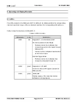
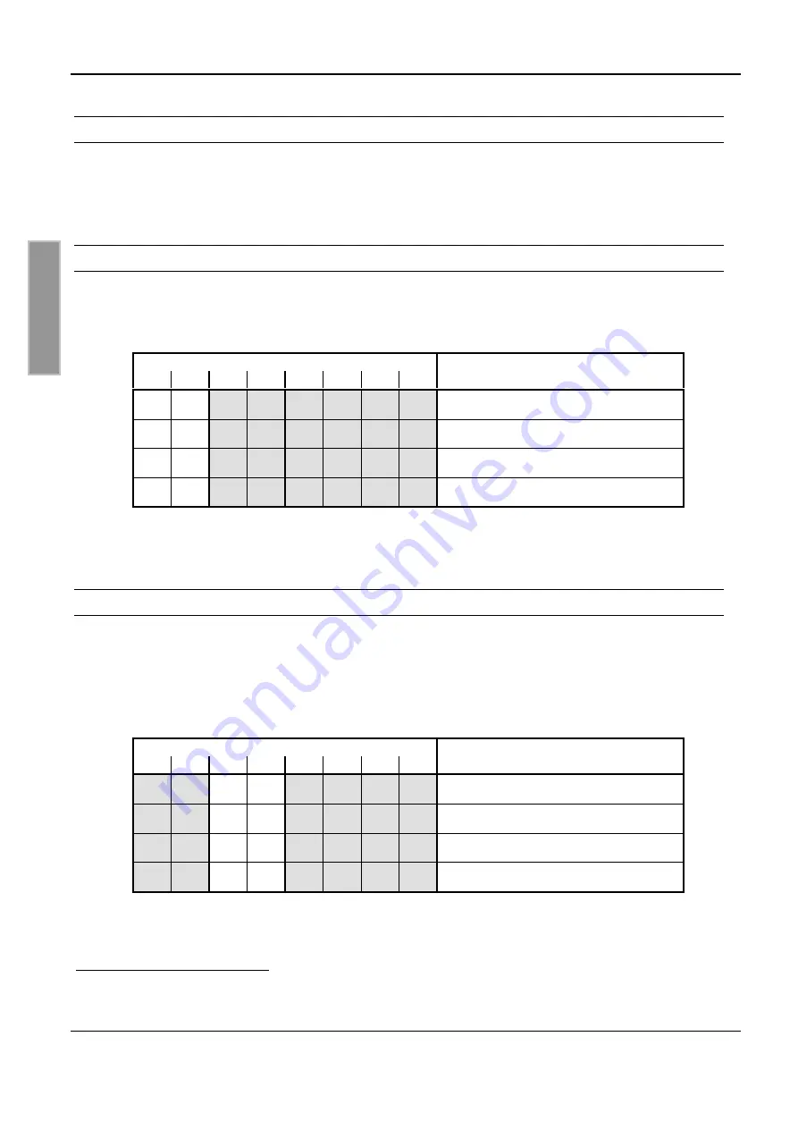
9.2. DIP Switch S1
DIP switch S1 can be used to set the various multiplexer modes and addresses. After changing the
DIP switch setting, you must perform a Power-Up Reset by briefly interrupting the supply voltage.
9.2.1. Setting the Modes
The modes are set using DIP switches 1 and 1. Table 3 shows a summary of the settings.
Table 3: Setting modes
DIP switch S1
Address
1
2
3
4
5
6
7
8
-
-
Reserved
-
ON
External Trigger Mode
ON
-
HF Communication Control Mode
ON ON
Reserved
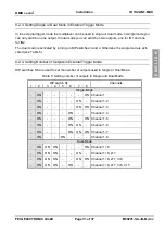
9.2.2. Address Setting in HF Communication Control Mode
The DIP switches can be used to set addresses for HF Communication Control Mode. DIP
switches 3 and 4 are used for setting the corresponding level
. Table 4 summarizes the settings for
the levels.
Table 4: Address setting in HF Communication Control Mode
DIP switch S1
Address / Level
1
2
3
4
5
6
7
8
ON
-
-
-
not used
ON
-
-
ON
Level 1
ON
-
ON
-
Level 2
ON
-
ON ON
Level 3
4
see 10.2. External Trigger Mode
5
see 10.1. HF Communication Control Mode
6
Reference Manual H30701-#e-ID-B.doc


