OBID i-
scan
Installation
ID ISC.ANT.MUX
FEIG ELECTRONIC GmbH
Page 22 of 37
M30201-1de-ID-B.doc
E N
G
L I S H
Content
6. Safety Instructions / Warning - Read before Start-Up !
23
7. Performance Features of the ID ISC.ANT.MUX 8x Antenna Multiplexer
24
7.1. Performance Features.................................................................................................... 24
7.2. Scope of Delivery ........................................................................................................... 24
8. Wiring and Installation
25
8.1. Installing the Enclosure ................................................................................................. 25
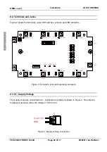
8.2. Terminals and Jacks ...................................................................................................... 26
8.3. X1: Supply Voltage ......................................................................................................... 26
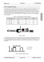
8.4. X2: Input (Opto-Coupler)................................................................................................ 27
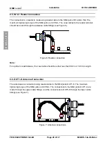
8.5. IN1-2: Reader Connection.............................................................................................. 28
8.6. OUT1-8: Antenna Connection........................................................................................ 28
9. Operating and Display Elements
29
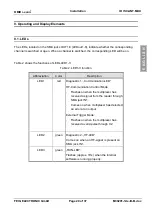
9.1. LEDs ................................................................................................................................ 29
9.2. DIP Switch S1 ................................................................................................................. 30
9.2.1. Setting the Modes ..................................................................................................... 30
9.2.2. Address Setting in HF Communication Control Mode................................................ 30
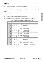
9.2.3. Setting Single or Dual Mode in External Trigger Mode .............................................. 31
9.2.4. Setting Number of Outputs in External Trigger Mode ................................................ 31
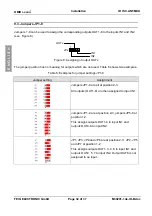
9.3. Jumpers JP1- 8............................................................................................................... 32
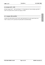
9.4. Jumpers JP11 - JP18...................................................................................................... 33
9.5. Jumpers JP19 and JP20................................................................................................ 33
10. Start-Up
34
10.1. HF Communication Control Mode ............................................................................... 34
10.2. External Trigger Mode.................................................................................................. 35
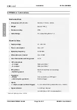
APPENDIX A: Technical Data
36

