


Identifikation System OBID
Page 20 of 28
FEIG ELECTRONIC GmbH
E N G L I S H
3. Installation
The device has been designed for wall installation. The wiring for the power supply may be laid
concealed or on the surface. For surface laying, open the casing at the provided place on its lower
edge.
NOTE:
•
The device not be installed directly upon conducting materials such as e.g. metal
surfaces, metal grids (reinforced walls) or metalliferous surfaces, as these surfaces
may reduce the detection range of the reader. A minimum distance of 10 cm to these
surfaces must be respected.
•
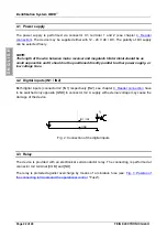
The distance between two units of the same type should not fall below 3 m.
•
Before final installation, the suitability of the intended installation place should be
tested.
Respect the installation order!
1. Wall installation:
•
Select installation place. The device should be installed on a surface as even
as possible.
•
Make openings for the supply wires and provide with included
twisting nipples.
•
Draw in wires.
•
Screw lower part of the casing to the surface.
(recommended screws 4 x 40 mm button head screw or slotted pan head
screw).
2. Reader connection:
3. Initiation:
4. Close casing:
•
hang up the lid of the casing at the lower edge of the lower part of the casing.
•
screw lid of casing to lower part of casing above the transparent pane with
both included casing-screws.
5. Attach the transparent pane and fix the adhesive label:
Only after having completed and checked all installation works, the transparent
pane and the adhesive front label are being attached to the clean and non-
greasy casing.


